Examine Connectivity of a Power Network
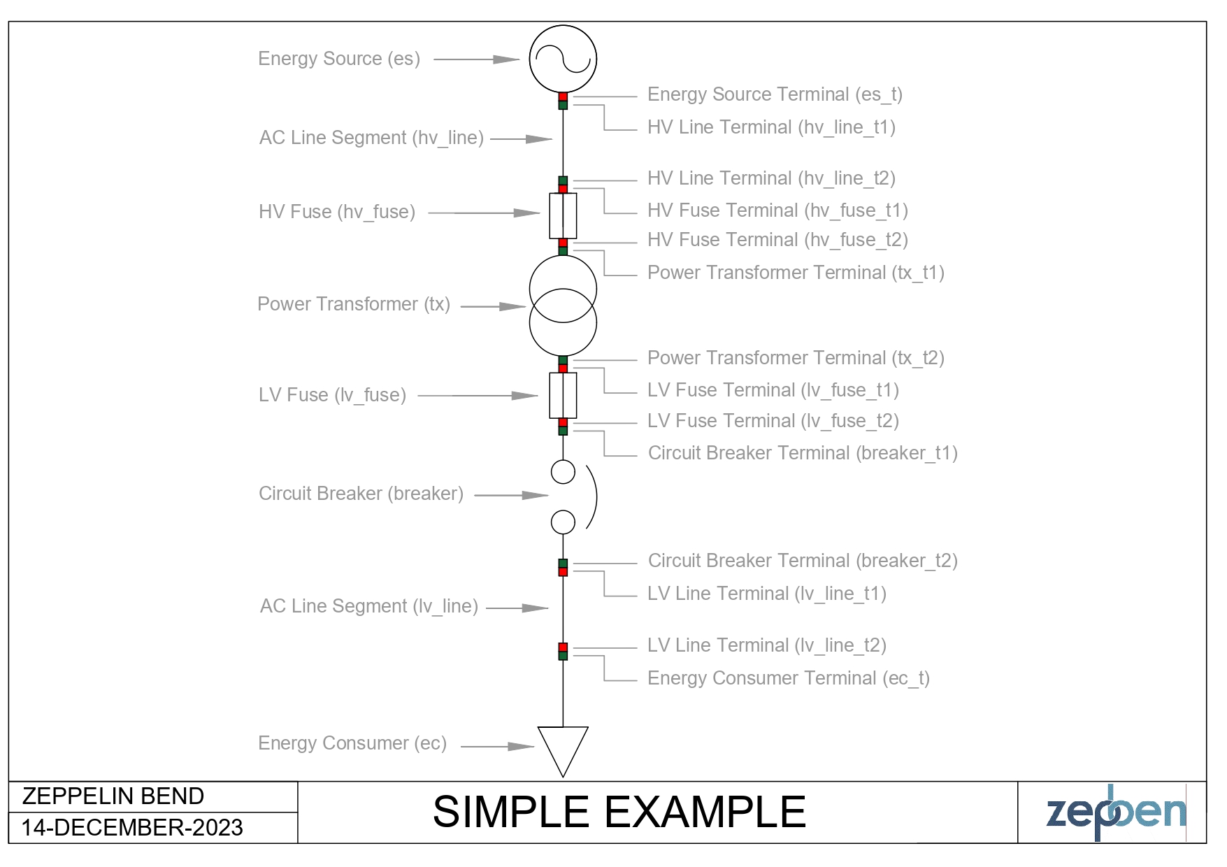
This example demonstrates how to examine the connectivity of a power system network. In this example, we will build a simple network shown below and test the connectivity between different equipment.
Getting Started
Ensure that you have installed and imported the required dependencies.
from zepben.evolve import EnergySource, AcLineSegment, Fuse, PowerTransformer, Breaker, EnergyConsumer, NetworkService, Terminal, connected_equipment, \
    ConductingEquipment, PhaseCode, connected_terminals, ConnectivityResult
Part A: Create a Network (Simple Example)
Step 1: Create an Energy Source
An Energy Source is a generic equivalent for an energy supplier on a transmission or distribution voltage level.
Energy sources are the foundation of power networks as they provide the electricity needed for various applications.
To create an energy source, you need to use the EnergySource class. To connect this Energy Source to any other equipment, you need to create a Terminal (an AC electrical connection point to a piece of conducting equipment) for the energy source. Use the Terminal class to create a terminal for the energy source.
es_t = Terminal(mrid="es-t")
es = EnergySource(mrid="es", terminals=[es_t])
Step 2: Create the HV Line
The HV Line in this example will be created using the AcLineSegment class. AC Line Segment can be a wire or a combination of wires with consistent electrical characteristics, building a single electrical system, used to carry alternating current between points in the power system.
An AC Line Segment has two ends. Hence, you will need to create a Terminal for each end to be able to connect the Line to any other equipment.
hv_line_t1, hv_line_t2 = Terminal(mrid="hv_line_t1"), Terminal(mrid="hv_line_t2")
hv_line = AcLineSegment(mrid="hv_line", terminals=[hv_line_t1, hv_line_t2])
Step 3: Create the HV Fuse
A fuse is an overcurrent protective device with a circuit opening fusible part that is heated and severed by the passage of overcurrent through it. A fuse is considered a switching device because it breaks current.
The Fuse class will be used to create a fuse in this example. Note that a fuse has two ends, so you will need to create a Terminal for each end to be able to connect to other equipment in the network.
hv_fuse_t1, hv_fuse_t2 = Terminal(mrid="hv_fuse_t1"), Terminal(mrid="hv_fuse_t2")
hv_fuse = Fuse(mrid="hv_fuse", terminals=[hv_fuse_t1, hv_fuse_t2])
Step 4: Create a Power Transformer
A Power Transformer is an electrical device consisting of two or more coupled windings, with or without a magnetic core, for introducing mutual coupling between electric circuits.
A Power Transformer typically has two terminals, but may have one (grounding), three or more terminals.
In this example, we are creating a two-winding transformer, so the transformer will consist of two ends that will connect to other devices in the network as shown in the simple example diagram.
The PowerTransformer class will be used to create the Power Transformer, and the Terminal class for creating the terminal for the Power Transformer, as follows.
tx_t1, tx_t2 = Terminal(mrid="tx_t1"), Terminal(mrid="tx_t2", phases=PhaseCode.ABCN)
tx = PowerTransformer(mrid="tx", terminals=[tx_t1, tx_t2])
Step 5: Create the LV Fuse
Description: Same as Step 3..
lv_fuse_t1, lv_fuse_t2 = Terminal(mrid="lv_fuse_t1", phases=PhaseCode.ABCN), Terminal(mrid="lv_fuse_t2", phases=PhaseCode.ABCN)
lv_fuse = Fuse(mrid="lv_fuse", terminals=[lv_fuse_t1, lv_fuse_t2])
Step 6: Create a Circuit Breaker
A Breaker is a mechanical switching device capable of making, carrying, and breaking currents under normal circuit conditions and also making, carrying for a specified time, and breaking currents under specified abnormal circuit conditions e.g. those of short circuit.
The Breaker class will be used to create the Circuit Breaker in this example. Since a breaker has two ends, we will create a terminal at both ends so that the breaker can be connected to other devices.
breaker_t1, breaker_t2 = Terminal(mrid="breaker_t1", phases=PhaseCode.ABCN), Terminal(mrid="breaker_t2", phases=PhaseCode.BN)
breaker = Breaker(mrid="breaker", terminals=[breaker_t1, breaker_t2])
Step 7: Create the LV Line
Description: Same as Step 2.
lv_line_t1, lv_line_t2 = Terminal(mrid="lv_line_t1", phases=PhaseCode.BN), Terminal(mrid="lv_line_t2", phases=PhaseCode.BN)
lv_line = AcLineSegment(mrid="lv_line", terminals=[lv_line_t1, lv_line_t2])
Step 8: Create an Energy Consumer
An Energy Consumer is a generic user of energy - a point of consumption on the power system phases. May also represent a pro-sumer with negative p/q values.
The EnergyConsumer class will be used to create an energy consumer in this example, and a terminal will be created for the energy consumer so that it can be connected to other devices in the network.
ec_t = Terminal(mrid="ec_t", phases=PhaseCode.BN)
ec = EnergyConsumer(mrid="ec", terminals=[ec_t])
Step 9: Create a Network Service
Once you have created the devices, they need to be added to a Network Service.
A NetworkService is a mutable node breaker network model that implements a subset of IEC61968 and IEC61970 CIM classes.
It is essentially a collection of IdentifiedObjects, and they may be added and removed as desired.
The following code is used to add all the above created devices to the Network Service.
network = NetworkService()
for io in [es_t, es, hv_line_t1, hv_line_t2, hv_line, hv_fuse_t1, hv_fuse_t2, hv_fuse, tx_t1, tx_t2, tx, lv_fuse_t1, lv_fuse_t2, lv_fuse, breaker_t1,
           breaker_t2, breaker, lv_line_t1, lv_line_t2, lv_line, ec_t, ec]:
    network.add(io)
Step 10: Connect Objects
The final step is to connect the objects (created in Steps 1 to 8) and add it to the network (created in Step 9).
The connect_terminals function will be used to connect the two terminals, as follows:
- Connect Energy Source to the HV Line
network.connect_terminals(es_t, hv_line_t1)
- Connect HV Line to the HV Fuse
network.connect_terminals(hv_line_t2, hv_fuse_t1)
- Connect HV Fuse to the Power Transformer
network.connect_terminals(hv_fuse_t2, tx_t1)
- Connect Power Transformer to the LV Fuse
network.connect_terminals(tx_t2, lv_fuse_t1)
- Connect LV Fuse to the Breaker
network.connect_terminals(lv_fuse_t2, breaker_t1)
- Connect Breaker to the LV Line
network.connect_terminals(breaker_t2, lv_line_t1)
- Connect LV Line to the Energy Consumer
network.connect_terminals(lv_line_t2, ec_t)
Part B: Examine Connectivity of the Network
This section explores examples of connectivity analysis of power systems (particularly the simple example that was built using the above guide). This example provides functions to print connectivity results between different equipment and terminals, including information about nominal phase paths.
Functions
In this example, we will use two main functions to display the connectivity results.
- First, we will use the
fancy_print_connectivity_resultfunction to display a formatted representation of the connectivity result. This function takesConnectivityResultas an input and displays the source and destination terminals. It then iterates over the nominal phase paths and prints the phase information about the terminals. Note: ConnectivityResult is a class defined inzepben.evolvemodule. It is used to store the connectivity between two terminals, including the mapping between the nominal phases. This class is intended to be used in an immutable way. You should avoid modifying it after it has been created.
def fancy_print_connectivity_result(connectivity_result: ConnectivityResult):
    print(f"\t{connectivity_result.from_terminal} to {connectivity_result.to_terminal}")

    terminal_str_len = len(str(connectivity_result.from_terminal))
    for core_path in connectivity_result.nominal_phase_paths:
        print(f"\t{core_path.from_phase.name:>{terminal_str_len}}----{core_path.to_phase.name}")
- We will also use the
fancy_print_connected_equipmentfunction to display the connectivity results for the specified equipment, considering the specified phases. This function takesConductingEquipmentand an optionalphasesarguments as input. Note: ConductingEquipment is an abstract class defined inzepben.evolvemodule. ConductingEquipment are parts of the AC power system that are designed to carry current or that are conductively connected through terminals.
def fancy_print_connected_equipment(equipment: ConductingEquipment, phases=None):
    if phases:
        print(f"Connectivity results for {equipment} on phases {phases}:")
    else:
        print(f"Connectivity results for {equipment}:")
    for connectivity_result in connected_equipment(equipment, phases):
        fancy_print_connectivity_result(connectivity_result)
    print()
Example Usages
This section demonstrates how to use the above functions with different equipment and phase configurations.
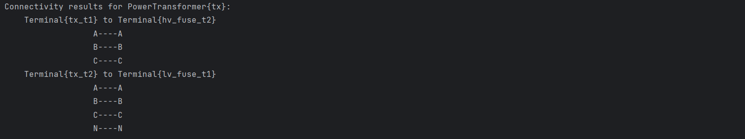
Example 1: The code snippet fancy_print_connected_equipment(tx) prints the connectivity results for the Power Transformer (tx). Since no phase information is provided, the default=None is used.
Output:
Example 2: The code snippet fancy_print_connected_equipment(tx, phases=PhaseCode.N) prints the connectivity results for the Power Transformer (tx), considering only the N phase.
Output:

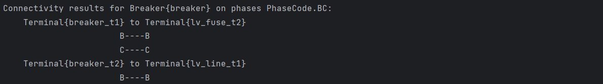
Example 3: The code snippet fancy_print_connected_equipment(breaker, phases=PhaseCode.BC) prints the connectivity results for the Breaker (breaker), considering only the B and C phases.
Output:
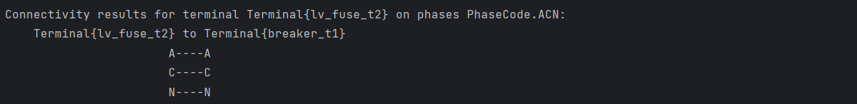
Example 4: The following code prints the connectivity results for the terminal lv_fuse_t2 with phases ACN using the connected_terminals function. Note that connected_terminals is essentially connected_equipment where only one terminal is considered.
print(f"Connectivity results for terminal {lv_fuse_t2} on phases {PhaseCode.ACN}:")
for connectivity_result in connected_terminals(lv_fuse_t2, PhaseCode.ACN):
    fancy_print_connectivity_result(connectivity_result)
Output: