Using the SINCAL Model
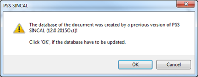
Once the process is complete, the model can be opened directly in SINCAL. The export process builds a SINCAL version model according to what is selected in the Target Version in the exporter, so you will get a dialog box asking you to confirm the upgrade if you are exporting older version and running a more recent version of SINCAL. If you are running an earlier version of SINCAL, the model will not load.
After pressing the OK button, the model should load successfully, and a display similar to the screen shot below should be produced. Most often, the display will be geographic, though in rare cases, the output network will be shown as a schematic (this will depend primarily on how the network is stored in EWB).
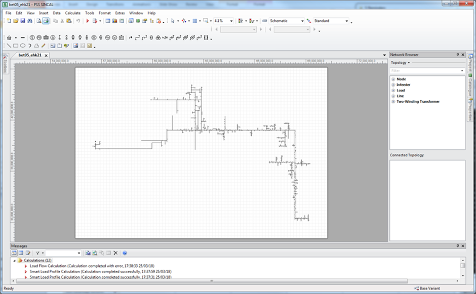
The network will generally be ready to run analysis immediately, though depending on how the load and fault level data was populated, you may need to undertake some additional steps to get that ready.
For MV only networks, distribution transformers are converted to loads; the distribution transformer itself may or may not be created depending on your settings. The P & Q values will be set according to the options selected in the Power Export preferences.
HV customers are also included as load points. If data is available from the EWB Load Server, these will be populated by the exporter as well.
Regulators are modelled as two winding transformers, using transformer models from the SINCAL standard database or the defaults of the SINCAL exporter for any data not stored in EWB.
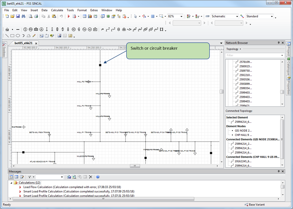
Switches and Circuit breakers are included in the model, as illustrated below. If the device is normally open, it will be exported in that state.
Isolation transformers are modelled as either two winding transformers, or as aggregated load points, depending on the options chosen, as described in the following sections.
Other network elements, such as capacitors and DER will also be created. Protection equipment, with settings, may also be created depending on the exporter settings and the information available in the input database.
Handling of SWER and single-phase network
If the Simplify SWER option is not picked, SWER is modelled as conductors with only a single phase (determined by the input data), with an isolation transformer connecting two phases on the two or three phase backbone to a single phase SWER line.
The isolation transformer will have its winding set to W1, W2 or W3. The following combinations can be used:
| TX Winding | SWER Line and Load Connection Types | Connected Phases |
|---|---|---|
| W1 | L1 | 1 and 2 |
| W2 | L2 | 2 and 3 |
| W3 | L3 | 1 and 3 |
Simplifying SWER
Simplifying SWER line results in all the connected load downstream of the isolation transformer being turned into an equivalent load, and the Isolation transformer being turned into a load point connected to the upstream network.
The option is enabled by ticking the Simplify SWER option under the export options.
Infeeder placement
Depending on the use of the “One Infeeder per Feeder” option, either (in the case the setting is on), one infeeder is created for each individual feeder, or, (in the case the setting is off), one infeeder is created for each zone, and is placed at the centre point of all feeder circuit breakers. This can result in some messy looking displays, as illustrated below for BQ zone substation, when all feeders are selected.
In the case where one infeeder per feeder is created, the infeeders will be grouped together in a horizontal line with a frame placed around the collection.
Finding Elements
Generally elements should be named as they were named in EWB, and should be findable in SINCAL through the find function (Ctrl-F). The original ID values are usually stored as a ‘Master Resource’ value, usually under ‘Additional Data’. These values can also be searched through the options of the SINCAL find function.
Note that in some cases names might be changed from their original values. The most common causes for this would be if the original element has been transformed in some way, such as when multiple line segments are merged together by the exporter to create a single conductor segment. When merging, the exporter will name the new element after the first and last segments merged, with the word ‘to’ between the names, eg. “Line1 to Line5”. Other merged lines are not included in the new name.
Sometimes the name of an element is too long for the SINCAL field, and will be truncated to fit. In such cases, the end of the name is cut off.
Checking the results
Reviewing the log from the file creation can give a good check of anything that went wrong, or was unexpected during the file creation process. The “WARN” and “ERROR” messages in particular should be used to find issues.
If using the load data from the server, it is a good idea to check the results of the model and load server data by looking at the feeder head currents from the SCADA system for the same day and time selected in the smart load solution.
Be careful about daylight saving time - all times reported by the smart load profile are in Australian Eastern Standard Time (AEST), not daylight saving time (AEDT).