Export Options Guide
The SINCAL model output can be configured in a number of ways.
Settings must be saved against a profile for them to apply, if you open up the options menu and change settings, then close the menu, these will NOT be automatically saved.
The 'default' profile is a reserved profile that is configured in consultation with your admin upon deployment. You can change settings within this for an individual export, but if you would like to adjust any settings for all exports, you need to create a new profile.
How to set up a new options preset
-
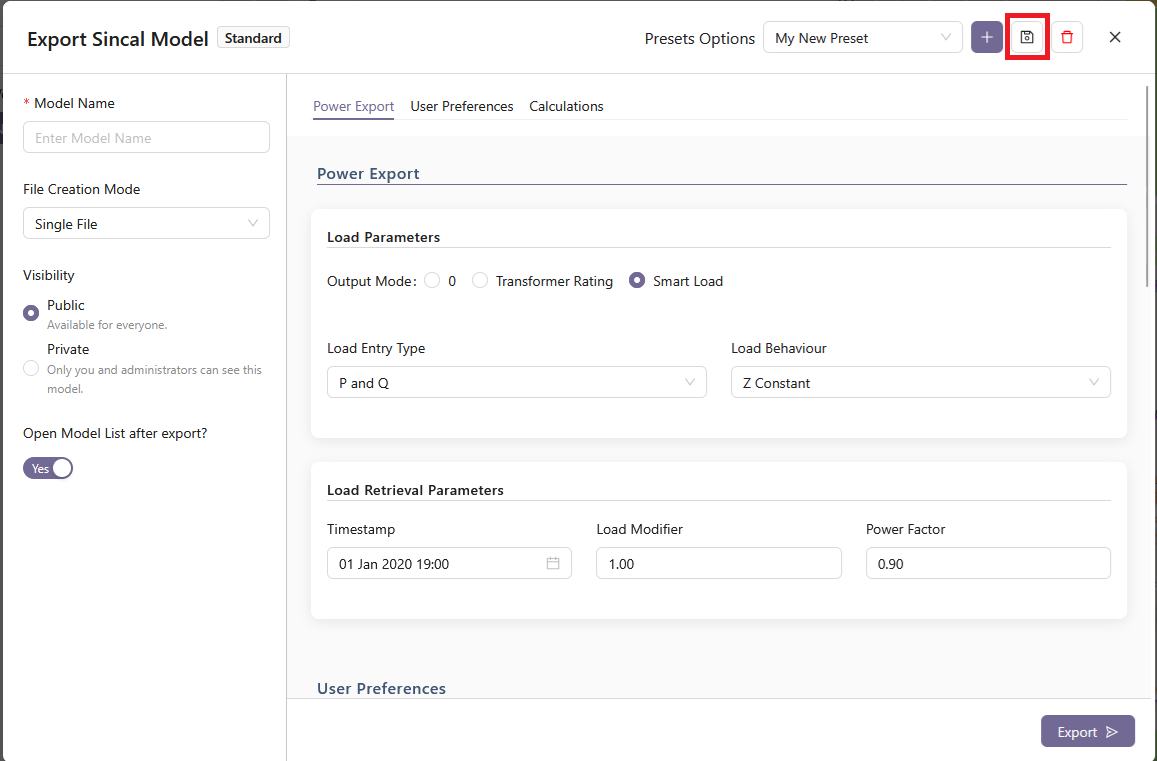
Go to "Export Model" from the SINCAL Export panel (you do not have to select anything for export if you only want to look at / configure export options).
-
Click the "+" button near the upper right, next to "Presets Options"

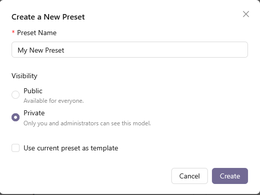
- In the Add New Preset menu, assign it a sensible name, and choose other preset options, and then 'Save Preset'.
-
Is Public?: Determines whether other users in your organisation can access this profile. Public profiles are stored on the server and visible to everyone in the organisation, while non-public profiles are only visible to you. Public models do not expire based on time, but are deleted on an oldest-first basis when the total storage used by all models exceeds the server threshold, set by Zepben for your organisation as part of your contract. This will typically be set to allow for many months of models under standard usage. If storage becomes a constraint, contact Zepben for assistance.
-
Use current preset as template: Sets the base settings for this preset as a copy of the currently selected preset. You will be able to change these settings once the new preset has been created. If this option is not selected, default values will be chosen.
-
- With the new mode selected, change whatever options you need across all three Option Tabs (Power Export, User Preferences, and Calculations), and then use the save button next to the add new preset button to save the changes to the preset.
You can temporarily make changes to a preset, including the default preset, and use them for the current export, without saving the changes. You can not save changes to the default preset, so the save button is disabled for this preset.
- If necessary, you can delete a preset using the delete button to the right of the save button. You cannot delete the default preset, or a preset that is not yours.
Options Detailed Explanation
Next we will detail the impact that each option has on the output and what the options mean.
Power Export Section
The Power Export section controls how load is configured in the output model.
Output mode controls how the power values are populated. The various options are explained here.
0 mode
The P and Q values will be zero for all loads.
Transformer rating mode
The P and Q values will be written using the nameplate rating (when available) of the transformer. This approach will only work for MV networks; if LV network is attached to the transformer, any downstream loads will not be populated this way. If nameplate rating is not available, the export will use a smart load reading for the load (if this is available). If neither method is available, the load will be set to zero, and an error message will be generated. Depending on the EWB server, and the data that was used to populate it, utilisation information for the transformer might be available. If this data is available, it will be set in the fields fS, fP and/or fQ as appropriate for the load entry type.
The fields within the Transformer Name Plate Rating Configuration options will control how the rating is converted into a load:
Percent (%) Utilize sets the load to be a percentage of the nameplate value, and the Power Factor sets the power factor of the load.
Note that the utilisation information that might be available from the server is different from the % Utilize used as a program setting, and both will be applied if set.
Smart load mode
The P and Q values will be written using the power reading from the server for this distribution transformer at the time specified in the Timestamp field. The Load Retrieval Parameters frame controls the options for loads that are retrieved using this method. Using this method requires that load data be set up and available on your load data server for the date selected. Check with your system administrator if you are not sure about the availability of load data on the server.
Load Entry Type specifies how the load values are entered, which is a subset of the options normally available in SINCAL:
- P & Q
- S & cosphi
- P & cosphi
- S, cosphi and Voltage
In all cases except the last, the voltage value in the load will be set as a percentage voltage, with a value of 100%. For the S, cosphi and Voltage option, the voltage will be set to the load’s default voltage as a value in volts (eg. 11 kV or 22 kV).
The Load Behaviour field corresponds to the same field in the SINCAL load entry, which controls the relationship between the voltage at the load and the amount of power it consumes. The available options within the exporter allow the specification of constant power, constant current or constant impedance loads. See the SINCAL documentation for more information on how these options are used.
User Preferences Section
The User Preferences section provides general options for the profile and the set up of the output SINCAL file. These options control the behaviour of the exporter when building the model, the output SINCAL version, the base template the SINCAL file is built from, and the local standard database used.
Options
Simplify Iso Transformers
If the Simplify Iso Transformers option is selected, SWER network (downstream of SWER isolating transformers) will not be included in the model, and a single load will be placed at the location of the isolating transformer, representing the sum of all downstream distribution transformer load. The load’s value will be set in different ways depending on the options set in the Power Export tab:
-
If the Smart Load option is set, and load data is available from the server, the load at the isolating transformer for the selected time will be used.
-
If the Transformer rating option is set, the load will be set according to the rating of the transformer. If utilisation data is available from the server for the isolating transformer, this will be set in the fS, fP and/or fQ fields as appropriate.
-
If the Zero load option is set, the load at the isolating transformer will be set to zero.
Using this option, in combination with the Ignore Phasing Data option can generate an entirely balanced network representation if this is needed.
If the Simplify Iso Transformers option is not selected, then SWER network will be represented within the output file.
Ignore Phasing Data
The Ignore Phasing Data option will instruct the exporter to ignore any data on phasing coming from the source information. Instead, all lines and elements will be treated as three phase, unless they are a SWER isolator or in network downstream of a SWER isolator. This option is intended to be used in cases where incorrect phasing data in the source information is leading to problems within the exported file, or where a balanced network is required as the output.
Create Embedded Generators
The Create Embedded Generators option will create representations of DER at distribution transformers (when the LV network is not modelled). This option relies on information supplied within the Input Database (which is uploaded through the Admin panel). If the option is used, and data is supplied for the distribution transformer, a DC infeeder will be created adjacent to the load, with capability to supply the specified amount of power. The DC infeeder will be switched out by default.
Split Delta on SWER Only
Split Delta on SWER Only refers to the creation of 2 phase (180 degree phase separation) LV systems. By default, the exporter will create a 2 phase LV system below a distribution transformer if the transformer has a delta secondary winding and is connected to either a single phase or SWER network (ie. any connection that is not L123 in SINCAL). Checking this option will mean that the transformer must be connected to a SWER (ie. L1, L2 or L3) system on its upstream side in order for a 2 phase LV system to be used, and the exporter will not create 2 phase systems in the LV for single phase MV network.
LV Loads on Random Phase
LV Loads on Random Phase is intended for use when modelling LV systems, where customers are connected directly to a three phase line, and are known to be single phase, but which phase they are on is unknown. Selecting this option will randomise the phase of the LV load, ignoring any data on phasing for the customer load that comes from the server. Due to the random nature of the phase generation, files created at different times using this option will apply different phases to the same consumers - ie. the load phasing will not be consistently generated. This option should not be used in cases where loads are all modelled at distribution transformers with no LV network modelled.
Create Measurement Devices
The option to Create Measurement Devices will, if checked, create a SINCAL measuring device (for use with the Load Assignment module) at infeeders and at the end/beginning of network zones. The measuring device will be off by default and not have any measured data associated with it. The end/beginning points of network zones are identified according to the information specified for the Zone End Node Name Matching. Zone End Node Name matching is defined in the Backend Configuration, and will be set by your administrator. You can ask Zepben for help with Zone End Node Name matching if your measurement devices are not showing up in the correct places.
Create Protection Devices
If this option is selected, Protection Devices will be created in the SINCAL model, provided the appropriate SINCAL protection database has been provided and kept up to date within the configuration data of the exporter. Protection device and settings information will also need to be provided in the Input Database. Both of these databases are specified through the Admin page. For more information, consult Zepben.
Remove Unnecessary Lines
Delete Duplicate Conductors
This option will remove duplicate lines, which are defined as lines with the same start and end points, same length and same impedance characteristics. This description might also cover parallel circuits in some cases, so deleting duplicate lines might not always be the correct option for your network. For this reason, the option is not checked by default, but users can enable it if they choose.
Delete Zero Length Dangling Conductors
A zero length dangling line is defined as a line that is only connected to the network at one end (ie. its far end is not connected to anything), and which has a length of zero. Such lines might exist as artefacts from the process of importing the data into the EWB server; short lines that were necessary in the originating system, but which just create clutter within SINCAL. These lines can be removed if the user would like. If the user would like to only do this for lines without any switches, or for lines without any open switches, these options are also available for selection under the Dangling Line Removal Type drop down.
Conductors
Do Not Merge Conductors
This option will prevent the exporter from combining similar lines together. Normally, to reduce the complexity of the output model, if two adjoining lines:
-
Are of the same impedance, rating and type; and
-
Do not connect to any third element at their common point of connection
They will be merged into a single line within the output SINCAL model. If this option is selected, the lines will not be merged, and the original number of conductors will be preserved in the output model. This can be useful if you wish to retain a 1:1 correlation with the original data source for the lines.
Retain Zero Impedance Lines
By default, a line that has all of its impedances set to zero will be treated as ‘suspect’ and have its parameters set to match those of the suspect line type specified. However, this behaviour can be overwritten by checking the Retain Zero Impedance Lines checkbox. If this box is checked, zero impedance lines will remain in the output network with their original data.
Default Parameters
Transformer Control Side
There are two settings, to either place the transformer controllers on the primary side or the secondary side of the transformers.
Infeeder Voltage Percentage
This gives the percentage of voltage that should be set for each SINCAL infeeder element.
Default Capacitor Size (MVar)
This gives the size for capacitors which are not linked to a standard type and do not have sizing information in the data stored on the server. The unit is in MVar, so a value of 1 would be a 1 Mega Volt-Amperes Reactive capacitor.
Calculations
Load Flow
Type
The Load Flow Type will set the corresponding parameter within the SINCAL Calculation Settings.
Network Level Line/Cable Temp.
Network Level Line/Cable Temp. (temperature) will set the value of Overhead Line Temp. (Tline) and Cable Temperature (Tcable) within the Network Level basic data for each network level (also called voltage level) that the SINCAL exporter creates.
Short Circuit
Type
The Short Circuit Type will set the corresponding parameter within the SINCAL Calculation Settings.
Temp. at End of Short Circuit
The Temp. at End of Short Circuit value sets the field of the same name within the Short Circuit Calculation Settings. It does not set the field of this name (Tend) for each individual line section.
Voltage Tolerance
Voltage Tolerance will set the value of Voltage Tolerance within the Short Circuit tab for each network level (also called voltage level).
The desired SINCAL version (eg Version 18, Version 20, etc) is set via the backend settings, as described in the Advanced Options section below. Generally speaking, later versions of SINCAL will have no issues with files created for earlier versions but not the other way around, e.g. SINCAL 20 can open a SINCAL 18 file, but SINCAL 18 cannot open a SINCAL 20 file. We recommend that as an organisation you decide the earliest version of SINCAL used and Zepben can set that as the default.
Advanced Options
There are some advanced and/or rarely altered options of the SINCAL exporter tool that are not currently directly editable in the web version of the tool.
If you require these options to be changed, this can be done by exporting a profile in the desktop version, and uploading it to the SINCAL Exporter Configuration section in the Admin tab.
Depending on your organisational setting, this tab may not be available to all users, so if you can't see it, speak to your System Administrator
There is only one setting available through these back end configuration settings that is not editable via the desktop front end, which is explained in the section below.
If you require any of these settings to be changed on more than a one-off basis, speak to Zepben about it, we may be able to add those options into the Web Version at a later date for your convenience.
Back end specific settings
By default, not all nodes that are switches within EWB are created as switches in output SINCAL models. This is due to some models having isolators connected on either side of a circuit breaker, or similar arrangements, that would result in clusters of switches in the SINCAL model. Such clusters are not likely to be necessary for network planning purposes. However, the ability to control which switch symbols in EWB are converted into switches in SINCAL is available for control through the configuration variable switchSymbolTypes, which is a part of the exportOptions within the configuration file.
The value of the configuration variable is a single integer number, determined by summing together the appropriate values from the symbol types that you wish to have converted to switches. Each symbol type is assigned an integer value, shown in the table below:
| Symbol Type | Integer |
|---|---|
| FEEDER_CB | 1 |
| CB | 2 |
| FUSE | 4 |
| ISOLATOR | 8 |
| RECLOSER | 16 |
| BROKEN_BRIDGE | 32 |
| GAS_INSULATED | 64 |
| LIVE_LINE_CLAMP | 128 |
| SWITCH | 256 |
| ARC_CHUTE | 512 |
| BRIDGE | 1024 |
| FLICKER_BLADE | 2048 |
For example, the default symbols converted to switches (CB, FEEDER_CB, RECLOSER, SWITCH, GAS_INSULATED, FUSE, ARC_CHUTE, LIVE_LINE_CLAMP and BRIDGE) sum to 2007, so this is the default value for this configuration variable.
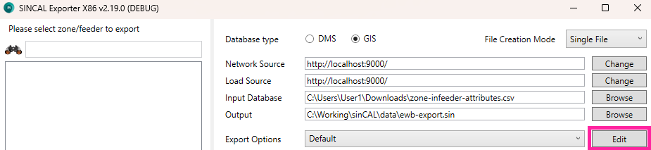
How to export settings from the Desktop Version
You should speak with a System Administrator for help with this process.
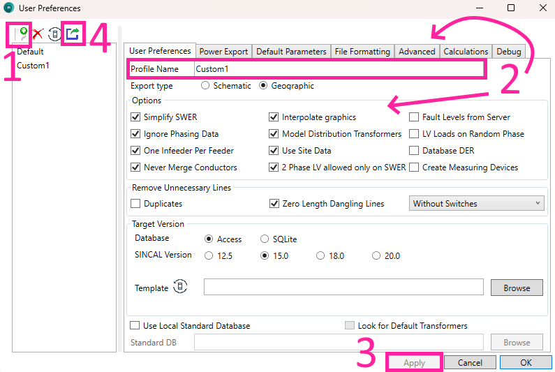
In the desktop version, click the 'Edit' button.
-
From the 'Default' profile, make a new profile via the 'Create New Profile' button.
-
Give your profile a new name, and make any desired changes.
-
Save the profile via the 'Apply' button.
-
Export the profile via the 'Export Settings for Web Version'. The export option is only available if the selected profile does not have unsaved changes.
This exports the currently selected profile to a directory, in two files, a front-end and back-end file. Each file will have the current date in their filename.
These settings can then be imported to the web version.
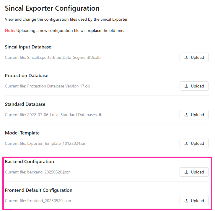
Import settings from the Desktop Version
- Go to 'Admin' in the top bar:

- Select 'SINCAL Exporter Configuration'

- Upload the backend and frontend files via the 'Upload' button. This will replace the old settings file.