Frequently Asked Questions
This page is written primarily from the perspective of the Desktop Version. For help with things in the web version, please ask Zepben if you get stuck.
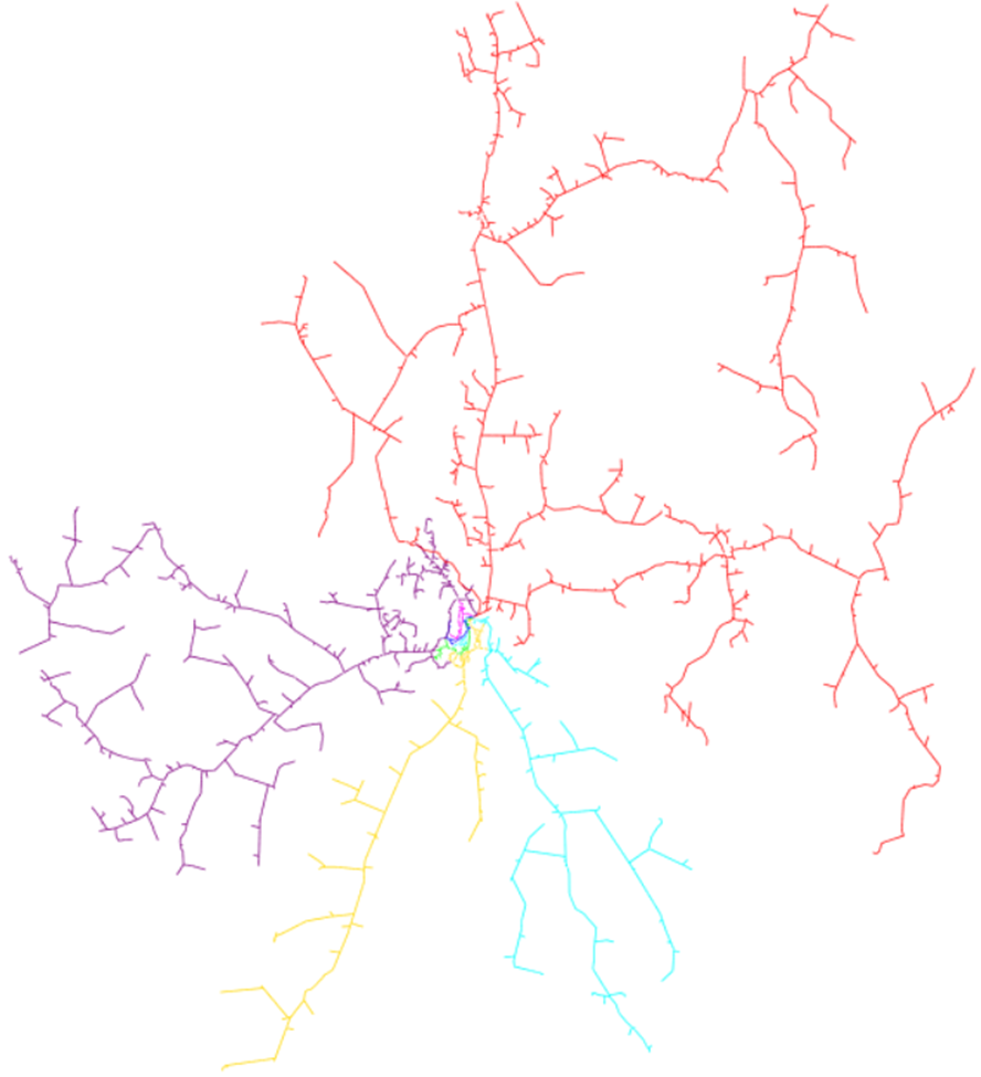
The SINCAL network diagram is cluttered – can it be neater?
In cases where there are a lot of assets close together, the resulting network can become a mess of overlapping switches, elements and text – see the example below.
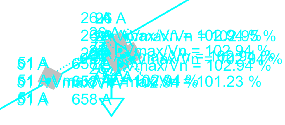
Obviously it is difficult within this network to read results or understand the connectivity. One way to resolve this kind of problem using the SINCAL exporter is to look at the Formatting settings. The default formatting settings are shown below:
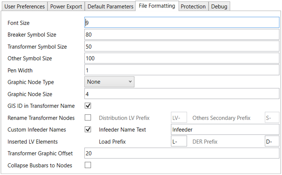
Depending on the network in question, and the way that it is drawn in EWB (which will ultimately depend on how it is drawn in the original source data system), these settings might be appropriate, or they might need to be adjusted for best viewing results.
As a general rule, the default settings tend to be reasonably appropriate for rural networks, where there is a reasonable distance between elements. The settings allow for network elements and results to be viewed at a mid level of zoom.
However, in cases such as the network shown above, it might be more appropriate to adjust the file format sizes to draw the network substantially smaller. For example, below are settings typically used for networks that are high density.
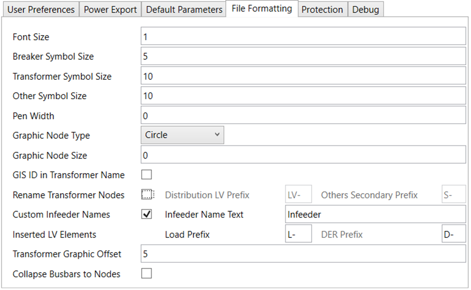
This results in the below network, for the same area that was shown at the start of this section.
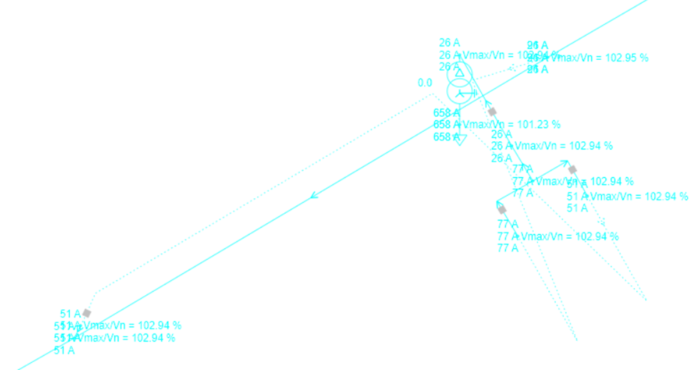
This is substantially easier to understand, and to see the connectivity. The disadvantage is that it is necessary to zoom in further to see the elements and read the results. However, in general this is a much more preferable approach in cases such as this. Remember that SINCAL allows the use of object types, as well as alternative views, both of which can also be good ways to declutter your view of the data. Object types may be configured within the SINCAL exporter also, and have the option to switch off text for particular elements or types of element. For more information on this, see the section on the Grouping Preferences form.
How can the default settings of the SINCAL file be adjusted?
There are numerous settings within the SINCAL file which do not directly relate to the electrical network, but more to the presentation and management of data. Such settings are typically workspace settings, and generally form a part of the information in the .sin file, rather than within the SINCAL database, such as:
- Annotation and filter settings / colour schemes;
- Links to standard databases or protection databases;
- Display of units for forms and tabular view.
For more information on what forms a part of the workspace, please see the SINCAL help file.
The SINCAL exporter does not create or edit the .sin file, and hence it does not create or change the workspace setting information. The SINCAL exporter uses a template .sin file, provided as a part of the settings, and copies this template file when creating new SINCAL files.
If you would like to adjust the workspace information that the SINCAL exporter uses, you should set up a template .sin file to suit your needs. You can use any .sin file that is set up as you would like, including from a SINCAL file that you are already using.
Desktop Version
The SINCAL exporter uses two template files when creating a new SINCAL file – a template .sin file and a template database file (either access or sqlite). The location is specified within the user settings, see the image below.
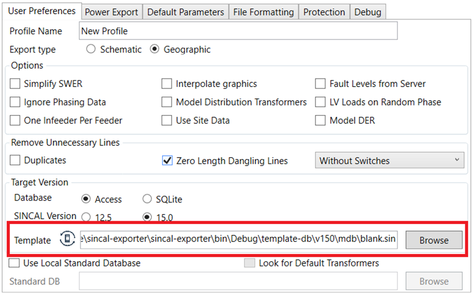
While the template location only refers to the .sin file in its name, the exporter will also expect to find a database (of the appropriate type) at the same location. Note that the location of the database should be in the same folder as the .sin file: SINCAL database files are normally stored in a directory named after the .sin file, but this is not how the SINCAL exporter stores template files.
If you are using multiple object types for your file (as set up within the Grouping Preferences form), you can also have annotations for these object types set up within the template file.
If you would like to adjust the .sin file used as a template for the SINCAL exporter, you can choose a new location within the settings, making sure that there is an appropriate blank SINCAL database in the same folder as the template as well. Generally the blank databases should always be the blank databases of appropriate version that are supplied with the SINCAL exporter. Blank databases of other SINCAL versions might cause problems with exported files.
Web Version
The .sin template file may be updated by a System Administrator, by going to the Admin tab of the web page (from the top menu), and going to the SINCAL Exporter Configuration section. The new .sin file may be uploaded in the Model Template section. See Export Options Guide (Web Version) for more info.
How are background maps set up in SINCAL?
When selecting Geographic as export type, a map can be inserted into the background in SINCAL. This requires some one time set up within SINCAL, as well as entering some settings for the specific file.
First time setup for background maps It is necessary to obtain and add an API key to a mapping service provider. You can go to Extras / Options / Background Maps within SINCAL to fill this information in.

Note that the SINCAL exporter does not come with an API key; these are generally obtained on an individual basis from the mapping service provider. The SINCAL help (linked from the Extras / Options form described above) can provide more information on which mapping services are currently available for SINCAL and how to obtain an API key.
Adding a background map to a specific SINCAL file Once the mapping service is set up as described in the above, the map can be set up for an individual SINCAL file. This is initiated by going to Tools / Background Map within SINCAL.
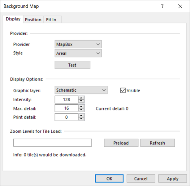
The first screen shows the provider, which should be as per the setup, and the type of map if options for this are available. It also shows the layer that the map will be displayed on, its intensity (how visible / opaque the map is) and the level of detail. Note that the default max detail of 16 might be too low if the map is going to zoom into to individual premises level, and further resolution might be available from the mapping service provider if a higher number is chosen.
The next tab, position, sets the basic positioning for the map.
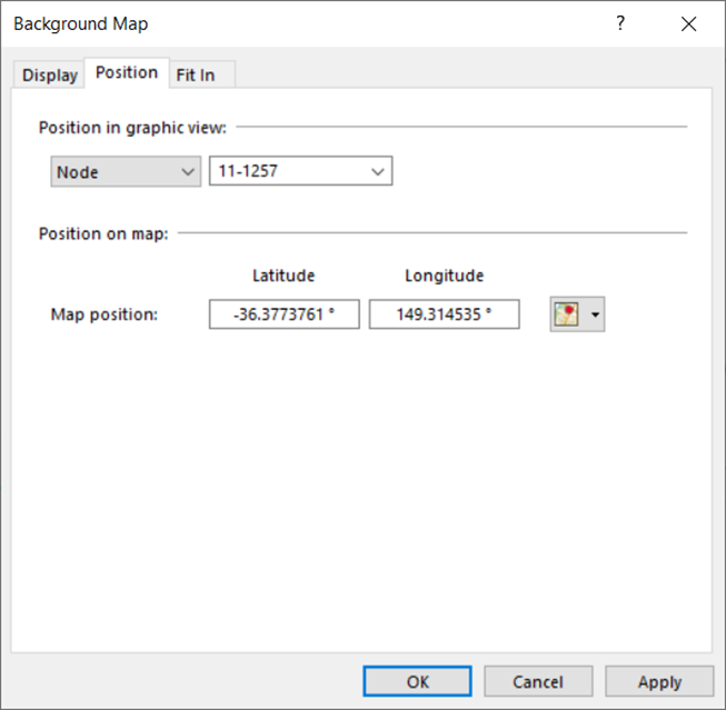
You can enter co-ordinates for a particular point on the map, but it is generally easiest to select a node from within the file. Since the SINCAL exporter will copy latitude and longitude information into the file from the EWB source system, this information will already be populated for any node that you choose.
Depending on the accuracy that you want from the map, this might be enough, and you can press OK to have the map drawn at this point. If you would like the map to be as accurate as possible, you can press OK, and then open the dialog again and go on to the next tab, Fit In.

Due to different methods of calculating the distance between latitudes and longitudes, and the differing ways lengths are calculated between the source systems and SINCAL, the geographic network might not be exactly the same size as the geographic map. Differences between the two can lead to distortions: at the position node, the map and the SINCAL network could match exactly, but as the distance from this point increases, distortions might mean that the network and the map do not line up as well.
The options on the Fit In tab are intended to alter the network to somewhat better fit the map. To do this, it is best to pick 3 nodes at the edges of the network. The exporter will help with this process, by changing the names of the nodes at the furthest extreme of the network to start with FN, and then the number 1, 2 or 3. You can choose the 3 FN nodes (using the filter could be helpful), and press Fit In. Using the Geographic option on the subsequent dialogue usually gives better results.
How can I resolve an issue with the load flow convergence?
A load flow might fail to solve for a large number of reasons. Both the SINCAL exporter and SINCAL itself will try to point anything that might be a cause, but ultimately it is hard to pinpoint every possible cause. However, the two most common causes of load flow failure are data issues or network overload. This section gives some tips on finding and resolving these problems.
Assessing the type of issue
There are some quick tests that can be made to determine whether the issue is more likely to be a load issue or a network data issue. The first is looking at when the load flow failed. Load flows that fail at one iteration, or before iterating starts, are generally due to data issues. Load flows that fail after this are more often due to load issues (or sometimes transformer issues). The SINCAL error message will give an indication about when the load flow failed, eg "Power Flow: Non Convergence - break after 43 iterations"
The above error indicates that the power flow failed after 43 iterations, indicative of the network loading being too high.
The other test that can be done is to adjust the load on the network, setting it to a much lower value to see if this will allow a load flow to solve.
One reasonably quick way to do this is to:
- Note the load input type in use in the file (P, Q and v, or S, cosphi and v for example), and the current value of the multipliers fP, fQ and fS. In general the exporter will create all loads with the load type.
- Select all the network in SINCAL (Ctrl-A).
- Go to Edit / Set Network Data / Load, and set either fP and fQ, or fS (depending on the type of load input you are using) to be a very small number. If you would prefer, you can use this dialog to multiply/divide P and Q or S directly.
- Once the load value is very small, try solving the load flow again. If it solves, that suggests that the original load values were too high.
- You can reset the fP, fQ or fS values, or under the multiplication of the load values by reusing the Set Network Data function.
Resolving Data Issues
Issues due to high load can often be resolved by looking at the load values within the tabular view, and finding values that are higher than they should be. Other solutions are to scale all loads (as described in the section above) and look for areas where there are still high current flows (or comparatively high current flows). SINCAL’s result filters can be helpful in this respect.
How do I set up and use Network Evaluations in SINCAL?
The SINCAL exporter will set up the exported network ready to use with several network evaluations within SINCAL. To use a network evaluation, your template file should be set up with the appropriate colour schemes and data: see the above section “How can the default settings of the SINCAL file be adjusted?” for information on how to change the template within the SINCAL exporter.
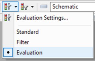
To use an evaluation within SINCAL, you can go to View / Evaluation Settings, or there is a button on the Network tool bar for this:
![]()
Under the Evaluation Settings, you can choose the evaluation in use, and the colour scheme for the evaluation. To change from colouring the network between the Standard, Filter and Evaluation network colourings, you can use the drop down menu next to the Network tool bar to change it:
Several evaluations are specifically useful for files created with the SINCAL exporter.
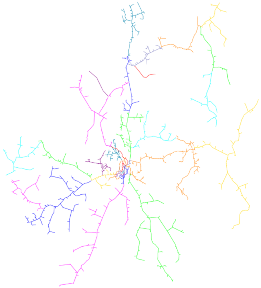
Network Areas
By default, within the exported SINCAL file, each different feeder is assigned to a different network area. Hence to quickly colour the network according to the original feeder assignment, you can use the Network Areas evaluation:
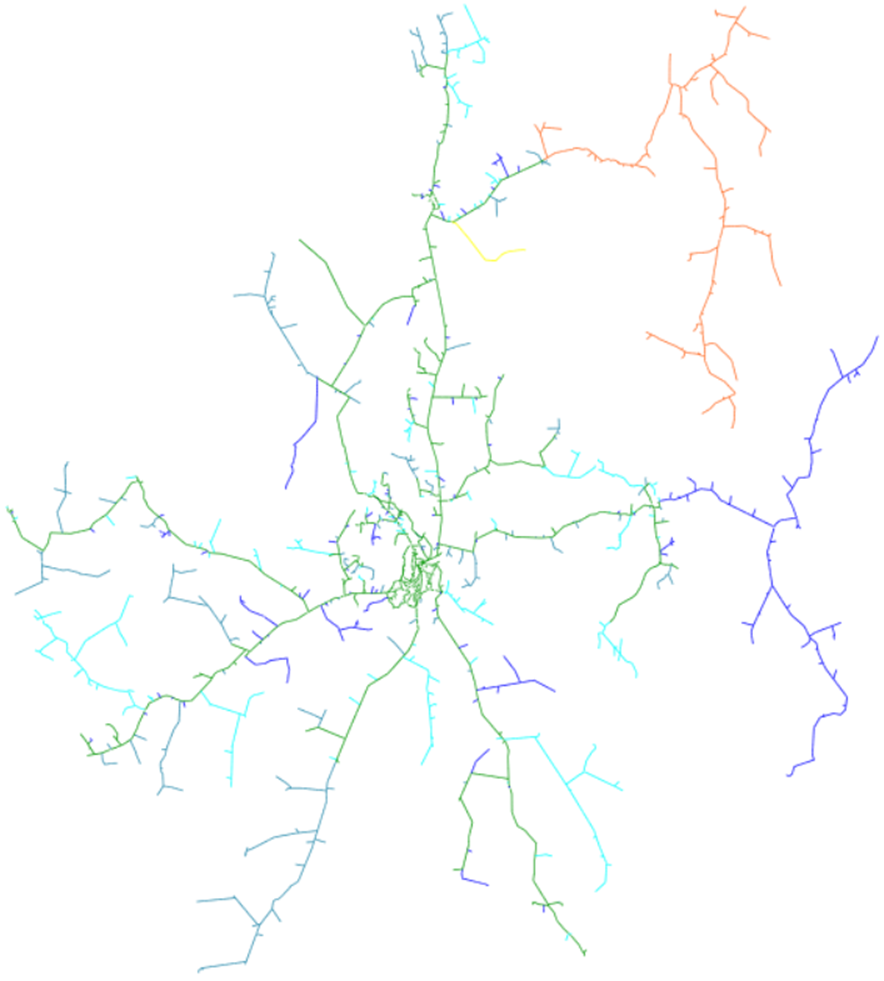
Network Zones
Feeders can be subdivided into zones: generally these are protection zones, but could be designated as you would like. The edge of a zone is marked according to nodes whose name fit the criteria of the Zone End Name Matching setting under the SINCAL Exporter options (in the Advanced tab in the desktop version, or configured through backend configuration for the web version). See the Export Options Form section in this help for more information. So long as suitable node names exist, the subdivision into zones should also work upon opening the exported SINCAL file.
Note that loads are also placed into network element groups based on which zone they are in. The network element group will be named after the recloser/breaker that forms the zone.
Network Phasing
As long as phasing exists within the network model, the evaluations Phasing and Connection Type should also yield useful results, colouring the network either according to the phase/s present, or the number of phases present respectively.
Network Element Group
There are several ways to potentially use a Network Element Group in concert with the SINCAL exporter. Please see the information below for the Network Element Groups that will be set up:
-
By default, the SINCAL exporter will create certain Network Element Groups automatically. These groups are:
- A voltage profile group for network infeeders, which should allow the automatic creation of voltage profiles along feeders.
- A load group for each network zone. The loads within each network zone will be assigned to a load group named after the element that defines the network zone. Network zones are defined using the information in Zone End Name Matching under the Advanced tab of the settings; see the information for the setting, and the detail above about network zone evaluations for more information about this. This is to allow easier scaling of loads in particular zones by grouping them together. It is not necessary to use or pay attention to this if it is not desired.
-
If you have set up your SINCAL Standard database such that the conductor type field “Conductor Info” contains the conductor material, you can also use the Network Element Group evaluation to colour the network according to conductor material. The SINCAL exporter will add lines to Network Element Groups if it reads the Conductor Info field as containing any of the following:
- ACSR
- Aluminium
- Copper
- Steel
Conductors with these types are added to their own groups. 3. If you have explicitly created a SINCAL grouping criteria set that includes a Network Element Group other than “None”, elements matching those criteria will be included in a network element group named as set within the grouping criteria. Desktop users can see the information in the Grouping Preferences Form for more detail. For web version users, these options are configured through the backend configuration file.
When colouring by Network Element Group, it is possible to quickly see network element groups across the network. In general it is much easier to see colouring for elements rather than nodes, so primarily option 2 above, as well as any elements included in groups by option 3 will be most visible.
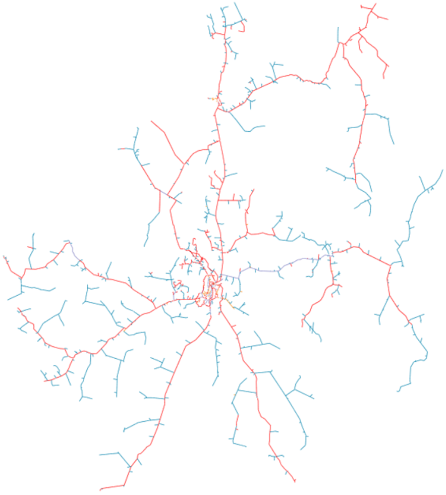
Layers
Network layers are used within the SINCAL exporter to highlight errors, or potential errors within the data. There are five potential layers that the exporter can create:
- Schematic: this is the default layer, that all elements will belong to unless an error or suspect condition is found for them.
- Missing Type: Data from the server did not contain type information for this conductor.
- Suspect Type: Data from the server contained a type that might contain incorrect data, ie. The type name itself indicates that the data is suspect (it contains “UNK” for unknown data), or the type information indicates that the impedance of the conductor is zero.
- Conductor Zero Length: This is used for a conductor branch that has a length of zero.
- Looped Elements: If an element is on a closed loop, it will be added to this layer.
Most objects will belong to the schematic layer in most networks.
Just as with the network areas or zones, it is possible to show the different layers via an evaluation. This evaluation can be used to quickly locate and visualise the extent of loops for example.
Items that exist on the other layers can also be found by using the SINCAL “Select by Type” option (Edit / Select / Select by Type). This dialogue includes the option to filter selection by layer, eg.
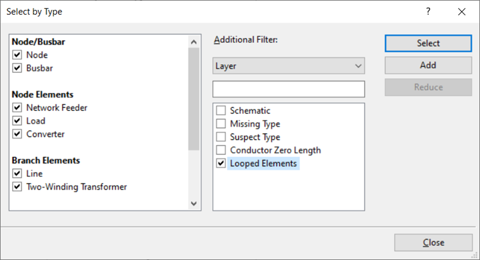
This dialogue is set up to select all elements on the looped elements layer, which will make these easier to find in a fully zoomed out view. It is possible to quickly select all types, by right clicking in the types window and choosing Select All.
How do I populate load values in the SINCAL model?
There are multiple options for populating load data. In general, populating load data is managed through the Power Export tab of the User Preferences. The basic meanings of the options are discussed in the help section for that tab, elsewhere in the documentation.
In general, the exporter is built to provide three different basic options for outputting load data, and two different more advanced systems. Depending on the data that you have available, you might use one or more of these options.
Basic Options
No Load Data – ‘0’ Load Option
The most basic option is the ‘0’ load option. This would be something to use if you do not want loads populated, or have no load data at all available within the EWB system, and cannot use transformer rating data (either because you are modelling to LV, or do not have transformer rating data either). This option is enabled by selecting ‘0’ as the Output Mode on the Power Export tab. When using this option, no load values will be set within the output SINCAL model.
Transformer Rating Option
The next most complex option is the ‘Transformer Rating’ option. If this is selected as the Output Mode then loads placed immediately at the LV terminal of a distribution transformer, or in place of a distribution transformer (depending on other options selected) will have their load values based on the size of the distribution transformer. If your model includes LV network, this option will not take any action for LV loads; it is designed for MV network only.
When using the ‘Transformer Rating’ option, there are two potential modifiers to the size of the load created in SINCAL. The first of these is the % Utilise field in the Transformer Name Plate Rating Config panel. The load value output to SINCAL will be multiplied by this percentage. It is also possible to set the value for the base load multipliers (‘fP, ‘fQ’ and ‘fS’) within SINCAL, if particular data within EWB itself is set. This option is not likely to be available to most users, as setting the data within EWB will require a data source and process to ingest it. However, if the value ‘transformerUtilisation’ has been populated within the EWB database, this figure will be inserted as a percentage into the SINCAL base load multipliers when using the transformer rating to populate the populate the load value.
The default power factor will come from the Power Factor value within the Transformer Name Plate Rating Config panel.
If a transformer does not have a rating, the SINCAL exporter will check to see if ‘smart load’ data is available (see the section below for more information about smart loads). For this reason, when selecting the ‘Transformer Rating’ option, options for the ‘Smart Load’ export will also appear. In the case that a rating is not found for a transformer, the options shown in the smart load panel will be applied for that transformer. If no smart load data is available for the transformer, the resulting load will be zero.
Smart Load
The third option for specifying basic load values is ‘Smart Load’. For this system, the load values are drawn directly from the EWB load data server, which in turn must support this option and have data populated for the loads requested.
The ‘Load Retrieval Parameters’ panel sets the options used by the ‘smart load’. The first value Timestamp sets the date and time to be retrieved. The Load Modifier specifies a factor that the stored load should be multiplied by (this could be used to simulate a forecast load for a future date for example). Finally, Power Factor sets a default value for the power factor to be used, in the case that the smart load data does not contain power factor information (some systems only record real power for example).
If smart load data is not found, transformer rating information, as detailed in the previous section, can be used as a fallback. This will only work for loads immediately at the secondary of a distribution transformer, so usually this will only be helpful for MV networks.
Advanced Options
The SINCAL exporter also allows for exporting to SINCAL load profile data, either through the use of load profile data, or operating points. Either of these options will populate the field ‘Profile 1’ of a SINCAL load, so the two options cannot be used in conjunction with one another.
Load Profiles
A load profile will be a series of load values over a period of time. This option makes use of the same data as used for ‘Smart Load’ – see the previous section within the Basic Options for more information about that. As with ‘Smart Load’ the EWB load data server will need to have the data available for the load point and date range requested for this feature to work.
To have the SINCAL exporter create a load profile with the export, the options are primarily under the Power Export tab of the User Preferences, in the panel entitled ‘Load Profiles’. Within this panel, you may check the option to create a load profile, and the start date for the profile. The end point for the profile is set by the Duration value under the Calculations tab. The profile will start at the date specified and continue for the duration specified in hours, with all data available from the source EWB load data server for this period added to the profile. (Note that the Start Date under the Calculations tab is the same Start Date under the Power Export tab, the field is repeated for convenience).
Operating Points
Operating Points are a concept used in SINCAL to represent particular moments of interest for a network. Commonly, these might be the time of maximum and minimum demand, though the Operating Points concept is not limited to only these. The SINCAL exporter allows the creation of Operating Points through populating data in the Input database, as well as configuring the User Preferences. Using the SINCAL exporter to create Operating Points should be faster and more consistent once the initial configuration is done.
The user preferences are set under the Advanced tab, within the ‘Operating Points’ panel. Here you can decide whether or not to implement operating points (remembering that they are mutually exclusive with profiles). Detailed information on the use of these options is available in the help section for User Preferences.
In essence, there are three ways that the Operating Points can be created, and each of these ways can be applied to three different element types. Operating Points can be applied to the following element types:
-
Loads
-
DC Infeeders (Converters)
-
Infeeders
For each element type, you can specify what type of Operating Point should be used (this is directly equivalent to the SINCAL type). Generally, an Operating Point will apply either a factor to the base load P and Q or S value, or an absolute value which will overwrite the base load value. The other value to specify would be the type of data that will be used for the Operating Point. The three options available are:
-
None
-
Shared Values
-
Individual Values
If None is specified, Operating Points will not be used for this type of Element.
Shared Values use a single set of Operating Point values across all elements of this type. This can be useful for applying factors, eg. Setting all load values to be 30% of normal value for a minimum load condition. If this option is selected, the necessary data for the option should be set up in the OperatingPointElementData table of the Input Database. You can find specific details of how to set up the data for that table in the relevant help section for the Input Database.
Individual Values use a different Operating Point for each element of this type. Each of these Operating Points must have their data specified within the Input Database, meaning that this can result in lot of data being required for this option. However, if the data is available, this can provide a good way to set up the Operating Points with detailed information. The relevant Input Database table for this option is the OperatingPointIndividualData table, and you can find more information about how to set up the data for that table in the relevant help section.
Regardless of which options are used for creating the Operating Points, the data in the OperatingPoints table of the Input Database must also be filled in.
I am updating the SINCAL standard database – what should I do with the SINCAL exporter?
The data in the SINCAL Standard database will normally be specific to your organisation and contain detail about conductor configurations and transformers that are specific to your network. You may need to update that data from time to time if you want to change records, add or remove new types or update the database version to keep up to date with later versions of SINCAL.
However, there are some implications of making changes to the SINCAL Standard database for the SINCAL exporter application, that you should definitely keep in mind when making changes:
- During the ingestion process (data going from the GIS into the Zepben Energy Workbench, aka EWB), a SINCAL standard database might be referenced. This will depend on the details of your ingestion process, which will be different from one user to another. However, if you are a user that makes use of the SINCAL standard database during the ingestion process, it is important that if you make changes to your SINCAL standard database you make sure to update this copy of it as well.
- If you change the name/location of the standard database and are using the Use Local Standard Database option, you will want to update the SINCAL standard database referenced in the SINCAL exporter options, and probably make sure that everyone is working from the updated file.
- If you are updating the transformers in the standard database and you are using both the Use Local Standard Database and Look for Default Transformers, there is a naming convention that you should continue to use. You can read more about that in the section for Export Options, under the User Preferences Tab options.
- The standard database in use by the SINCAL files that the exporter creates is linked in the template .sin file. If you update the standard database and change its name/location, you should also update the template file to reference the new name and location. You can read more about how to update the template .sin file in the FAQ question: How can the default settings of the SINCAL file be adjusted?
Common Errors and Warnings
Cable Type XXX has zero impedance, treating as suspect.
Default 'suspect' values from configuration will be used as impedance for this cable type.
When loading configuration data, the Exporter reads information from a library of conductor data kept on the EWB server. If any of the entries in this library have zero impedance (for values of R, X, R0 and X0), and you are not using the “Retain Zero impedance Lines” option, the exporter will give this warning when loading the configuration data. If this cable type is never used in the exported data, this will have no impact at all. If the named cable type is used, rather than having an impedance of zero, the line will instead use the values from the “Suspect” default line impedance set. There will commonly be one default impedance entry in the EWB server dictionary, so seeing this warning once for an export is often not a concern, particularly if the line is named something like 'ZEPBEN_ZERO_IMP_PLSI'. However, if the warning comes up multiple times, or for cable types that should definitely have impedance values entered, this could be a concern.
*X elements* on *Y Feeder* are connected to multiple feeders.
This might be a sign of incorrect source data.
This warning indicates that a certain number of elements (X) were found to be connected to more than one feeder. By far the most common cause of this issue is that an open point is missing, incorrectly connected or misconfigured.
This error can have a serious impact on the extracted network, as it can mean that parts of the feeder being built in fact belong to another feeder. Incorrect open points, as indicated by this error, can also result in parts of a feeder being missing.
This warning should be corrected by looking at the source information for the Exporter, and ensuring that open points are correctly placed and connected.