Export Options Guide
Output options are controlled by the options that appear on the main screen (as shown above), which contains options for where data is to be sourced from, and also the settings to be applied for the smart load flow control.
Output options relating to specific options about how the SINCAL file is built from the data may be selected from the Export Options drop down. These options may be created or configured via the Edit button adjacent to the drop down.
Main Form Options
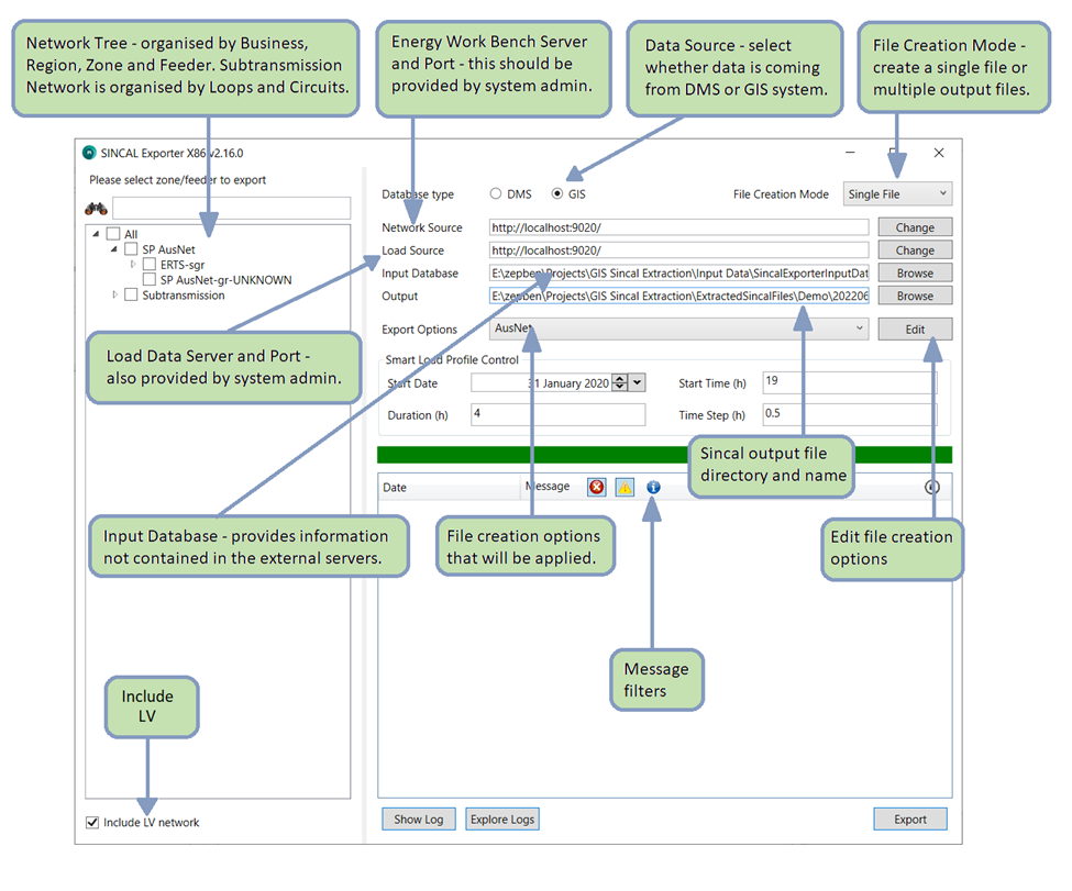 The first output option you will see is the data source type. This is used to select whether the data being exported into SINCAL is sourced from the DMS or the GIS. Differences between these data sources mean that this option should generally be set to match the original source system.
To the right of this is the option to choose the file creation mode. The selected zones or feeders can be joined together into a single file, or multiple output files can be created, with output feeders either grouped by zone substation, or generated per individual feeder. For these latter options, choose the “Batch by zone” or “Batch by Feeder” option here. For these file creation modes, the output file name must contain the text “zone” or “feeder” - this text will be replaced by the name of the zone substation or feeder which is created for each output file. All output files will use the same file creation options and output file folder. (If you have an ongoing need to automatically create files this way, Zepben has an additional tool that can do this for you).
Other options on the main form are used to indicate the servers (both for network data and for load data, though these may be the same). Your system administrator should be able to give you this information.
The next field down specifies where the input database file is located. This file can contain information which is not available from the server. Depending on your server data, and file creation options, this database might contain any, or none, of the data below:
Source Impedances: The source impedances will be used to set the fault levels at the infeeders (which are placed at the start of the feeder or zone substation). Depending on your EWB database, this information might come from the server instead; this can be selected in the export options.
Protection Settings: If the exporter is creating protection devices, settings for those devices can be placed within the input database. To create protection devices, information on the placement of the devices must be within the EWB database, and the selections for creating protection devices must be set within the export options.
Embedded Generation: Embedded generation options will place DC infeeders at distribution substations, where information about how much embedded generation exists within the distribution substation is available. To use this option, the selection for creating DER must be made within the export options.
Consult the input database section for more information on the layout of the input database and how to use it.
If you are not using any of the data from the input database, you should use the default empty CSV which is supplied with the Sincal exporter, “zone-infeeder-attributes.csv”. This CSV file can also be used to populate simple fault level data, but none of the other options. To populate source impedances with maximum, normal and minimum values, and/or protection settings, and/or embedded generation, a database should be used. The database can be in SQLite or MDB format.
The output file is the location where the exporter will create the exported SINCAL file. This can overwrite existing files in that location (though the exporter will give a warning prior to doing this).
Export Options
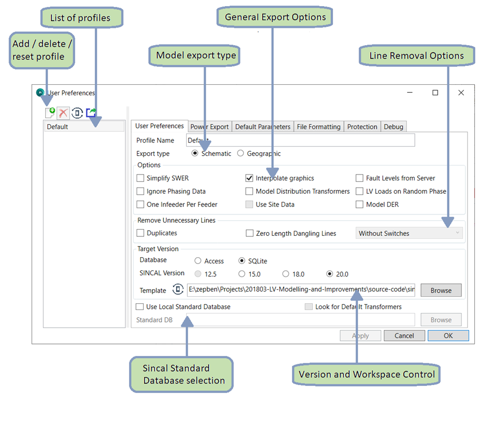
Using the Edit button on the main form will present all of the detailed options for controlling the export.
Profile Options
Multiple profiles can be set up to undertake exports with different setting combinations. These are controlled in the list at the left of the form. New profiles can be created, existing profiles deleted (one profile must always exist), and profiles can be reset to their default values with the options here. It is also possible to export the currently selected settings to a JSON format, suitable for use with the web version of the SINCAL exporter. This function exports the currently selected profile to a directory, in two files, a front-end and back-end file. Each file will have the current date in their filename. If you have access to the web version of the SINCAL exporter, these files should be helpful in creating settings file for that version. Note that this option is only available if the selected profile does not have unsaved changes.
There are a large number of options available for customising how the SINCAL model is built. The options are organised into various sections by tabs: the User Preferences tab, the Power Export tab, the Default Parameters tab, the File Formatting tab, the Advanced tab, and the Debug tab. The options on each of the tabs are explained in the following sections.
User Preferences Options
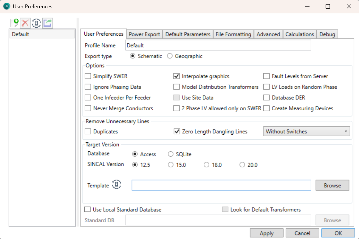
The User Preferences tab controls general options for the profile and the set up of the output SINCAL file. These options control the behaviour of the exporter when building the model, the output SINCAL version, the base template the SINCAL file is built from, and the local standard database used. Each option on the tab is discussed in this section.
The model export type controls the graphical layout used to generate the SINCAL model. It is only applicable to models sourced from DMS data. If a model is sourced from GIS data, the Geographic export option will automatically be applied. This is due to the availability of graphical data - the GIS system only stores a geographical representation of the network.
If the Simplify SWER option is selected, SWER network (downstream of SWER isolating transformers) will not be included in the model, and a single load will be placed at the location of the isolating transformer, representing the sum of all downstream distribution transformer load. The load’s value will be set in different ways depending on the options set in the Power Export tab:
-
If the Smart Load option is set, and load data is available from the server, the load at the isolating transformer for the selected time will be used.
-
If the Transformer rating option is set, the load will be set according to the rating of the transformer. If utilisation data is available from the server for the isolating transformer, this will be set in the fS, fP and/or fQ fields as appropriate.
-
If the Zero load option is set, the load at the isolating transformer will be set to zero.
Using this option, in combination with the Ignore Phasing Data option can generate an entirely balanced network representation if this is needed.
If the Simplify SWER option is not selected, SWER network will be represented within the output file.
Selecting the Interpolate graphics option will make the exporter create graphics for as much of the network as possible. Any node connected to another visible asset will be drawn at the same location. This will potentially cause many nodes to be drawn at the same location, but they can then be relocated manually which is not possible if there are no graphics.
Selecting the Fault Levels from Server option will instruct the exporter to request the server provide fault level information for the infeeders. The fault level data must be present on the server for this option to work, so check with the system administrator to make sure this can be done. If this option is selected, any source impedance data in the input database (selected on the main form) will be ignored.
The Ignore Phasing Data option will instruct the exporter to ignore any data on phasing coming from the source information. Instead, all lines and elements will be treated as three phase, unless they are a SWER isolator or in network downstream of a SWER isolator. This option is intended to be used in cases where incorrect phasing data in the source information is leading to problems within the exported file, or where a balanced network is required as the output.
Model Distribution Transformers is used when modelling MV distribution systems without LV network present. In such cases, loads can be represented either as a single load connected to the MV network, or as a distribution transformer and LV load. Selected this option means that the latter option, with a transformer, will be used. The data for the transformer can come for the SINCAL Standard database, or be a default transformer (defaults are also configurable within the SINCAL Standard database).
LV Loads on Random Phase is intended for use when modelling LV systems, where customers are connected directly to a three phase line, and are known to be single phase, but which phase they are on is unknown. Selecting this option will randomise the phase of the LV load, ignoring any data on phasing for the customer load that comes from the server. Due to the random nature of the phase generation, files created at different times using this option will apply different phases to the same consumers - ie. the load phasing will not be consistently generated. This option should not be used in cases where loads are all modelled at distribution transformers with no LV network modelled.
One Infeeder per Feeder is an option to choose to create a single infeeder for each feeder within the SINCAL file. The alternative (default) option is to create one infeeder at each zone substation, with all feeders joined to a common bus that the infeeder connects to. Note that the use of this option can impact on how the fault level / source impedance information should be specified within either the Input Database or the EWB server (if using the Fault Levels from Server option).
If you have zone substations with differing fault levels for different feeders (eg. a split bus arrangement), the One Infeeder per Feeder option will allow you to specify different fault levels on a per feeder basis within the input database. This can also work if you use the Fault Levels from Server option, rather than the input database.
Use Site Data is an option that can only be used with geographic network data (site information is handled differently for schematic based network data). If site data is available within the server information, it can be used to:
-
Help collapse regulators, allowing the exporter to understand which transformers, switches and connectors are within the regulator site, so that the output representation can be simplified; and
-
Improve representation of multiple distribution transformers at a single site; rather than the two transformers being stacked on top of each other, they can be separated slightly for easier viewing.
Note: this option is not recommended if you do not have site data set up within your EWB server data. Your system administrator should be able to tell you if this is the case.
The Database DER option will create representations of DER at distribution transformers (when the LV network is not modelled). This option relies on information supplied within the Input Database (specified on the main form). If the option is used, and data is supplied for the distribution transformer, a DC infeeder will be created adjacent to the load, with capability to supply the specified amount of power. The DC infeeder will be switched out by default.
Sometimes the EWB database contains extraneous lines that are not desirable within the output SINCAL file. Such lines can be removed with the Line Removal Options. There are two types of lines that may be removed:
● Duplicates: duplicate lines are lines with the same start and end points, same length and same impedance characteristics. This description might also cover parallel circuits in some cases, so deleting duplicate lines might not always be the correct option for your network. For this reason, the option is not checked by default, but users can enable it if they choose.
● Zero Length Dangling Lines: a zero length dangling line is defined as a line that is only connected to the network at one end (ie. its far end is not connected to anything), and which has a length of zero. Such lines might exist as artefacts from the process of importing the data into the EWB server; short lines that were necessary in the originating system, but which just create clutter within SINCAL. These lines can be removed if the user would like. If the user would like to only do this for lines without any switches, or for lines without any open switches, these options are also available for selection.
The option to Never Merge Conductors exists to prevent the exporter from combining similar lines together. Normally, to reduce the complexity of the output model, if two adjoining lines:
-
Are of the same impedance, rating and type; and
-
Do not connect to any third element at their common point of connection
They will be merged into a single line within the output SINCAL model. If this option is selected, the lines will not be merged, and the original number of conductors will be preserved in the output model. This can be useful if you wish to retain a 1:1 correlation with the original data source for the lines.
The option for 2 Phase LV allowed only on SWER refers to the creation of 2 phase (180 degree phase separation) LV systems. By default, the exporter will create a 2 phase LV system below a distribution transformer if the transformer has a delta secondary winding and is connected to either a single phase or SWER network (ie. any connection that is not L123 in SINCAL). Checking this option will mean that the transformer must be connected to a SWER (ie. L1, L2 or L3) system on its upstream side in order for a 2 phase LV system to be used, and the exporter will not create 2 phase systems in the LV for single phase MV network.
The option to Create Measuring Devices will, if checked, create a SINCAL measuring device (for use with the Load Assignment module) at infeeders and at the end/beginning of network zones. The measuring device will be off by default and not have any measured data associated with it. The end/beginning points of network zones are identified according to the information specified for the Zone End Node Name Matching: see the description of this option under the Advanced settings section.
The options within the Target Version section will determine the version and type of SINCAL database that is created. It also contains the template file that will be used as the basis of exported SINCAL files (this template file will include SINCAL workspace information, such as annotation and filter data). The user can select a template file, or use the defaults that come with the exporter. Note that there needs to be both a .sin file and a database file (.mdb or .db) in the template folder. The template database should match to the version of SINCAL being generated, and not contain any network data. Such databases are provided with the installation of the exporter. See the section on adjusting default settings within the FAQ for more information on this topic.
It is possible for the .sin file and the database file to be mismatched: if you need to use a .sin file containing specific workspace information, links to your standard type databases etc, you can use your own .sin file, even if it is a different SINCAL version to the database file. As above, it is recommended that the database files should always match to the SINCAL version being exported however, rather than substituting a different SINCAL version. This will allow SINCAL to properly update the databases when opening the files in another version.
The exporter can work with a SINCAL Standard Database as a Local Standard Database. This will generally require that the data on the EWB server contains the appropriate references to the local standard database, so that the exporter can tell which type of asset from the database a particular element should represent. Hence you should check with your system administrator which options might be available for you. There is an option to Look for Default Transformers as well: this option can be used if the EWB server database does not contain a reference to a standard database type, but the Local Standard database specifies transformers that can be used as defaults. Such transformers should be named within the Local Standard database so that they can be identified by the exporter. The naming convention should be as follows:
default-<Transformer Type><User Name>
The name should have "SWER" added to the end if it is a SWER distribution transformer.
Each of the fields enclosed with <> should be replaced with an appropriate value:
Transformer Type: one of “regulator”, “isolator” or “distrib” depending on the transformer type.
User Name: The user may enter their desired name in this space, bearing in mind that SINCAL limits the length of the type name field to 40 characters.
If this option is used, transformers which match the naming, and also have appropriate primary and secondary voltages, rating and vector group will be linked to the appropriate default transformer in the Standard Database. If no match is found, generic values, and no standard type, will be used at that transformer.
Power Export Options
The load values used and set up within the output SINCAL file can be changed through the options under the Power Export tab on the Export Options form.
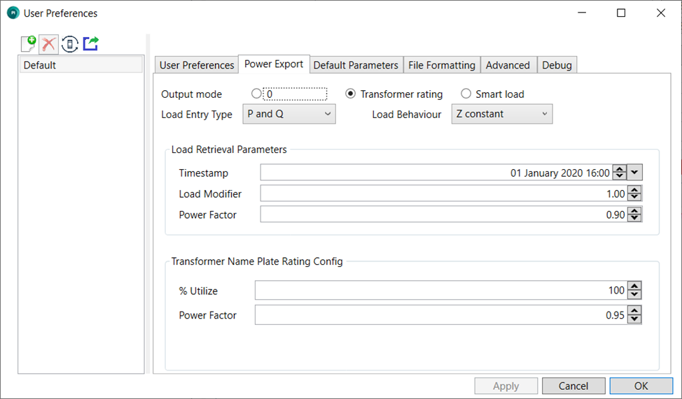
Output mode controls how the power values are populated. The various options are explained here.
0 mode
The P and Q values will be 0 for all loads.
Transformer rating mode
The P and Q values will be written using the nameplate rating (when available) of the transformer. If nameplate rating is not available, the export will use a smart load reading for the load (if this is available). If neither method is available, the load will be set to zero, and an error message will be generated. Depending on the EWB server, and the data that was used to populate it, utilisation information for the transformer might be available. If this data is available, it will be set in the fields fS, fP and/or fQ as appropriate for the load entry type.
The fields within the Transformer Name Plate Rating Config frame will control how the rating is converted into a load: % Utilize sets the load to be a percentage of the nameplate value, and the power factor sets the power factor of the load. Note that the utilisation information that might be available from the server is differ from the % Utilize used as a program setting, and both will be applied if set.
Smart load mode
The P and Q values will be written using the power reading from the server for this distribution transformer at the time specified in the Timestamp field. The Load Retrieval Parameters frame controls the options for loads that are retrieved using this method. Using this method requires that load data be set up and available on your load data server for the date selected. Check with your system administrator if you are not sure about the availability of load data on the server.
The other settings available in this form determine how the load is set up within SINCAL - Load Entry Type specifies how the load values are entered, which is a subset of the options normally available in SINCAL:
- P & Q
- S & cosphi
- P & cosphi
- S, cosphi and Voltage
In all cases except the last, the voltage value in the load will be set as a percentage voltage, with a value of 100%. For the S, cosphi and Voltage option, the voltage will be set to the load’s default voltage as a value in volts (eg. 11 kV or 22 kV).
The Load Behaviour field corresponds to the same field in the SINCAL load entry, which controls the relationship between the voltage at the load and the amount of power it consumes. The available options within the exporter allow the specification of constant power, constant current or constant impedance loads. See the SINCAL documentation for more information on how these options are used.
Default Parameters
These options relate to how data will be set if it cannot be found in the data from the server or other sources.
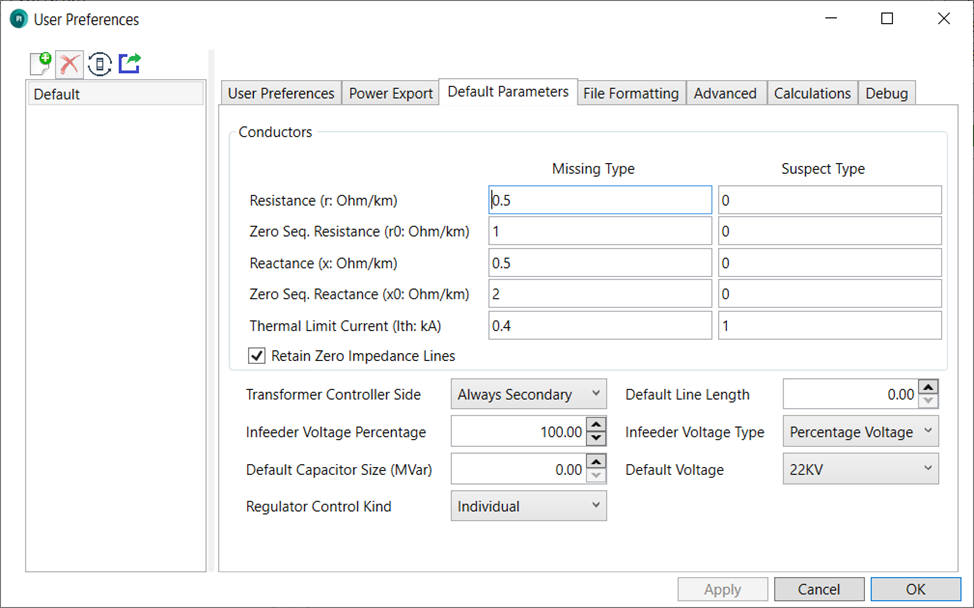
The values used for r, x, r0, x0 and a rating for missing or suspect lines types can be changed in the export tool by accessing the Conductors frame.
The frame will contain default values for missing and suspect line types, which will be used when dictionary data is not available or is appears incorrect (eg. all the values in the source system are zero). These values are set per profile, so each set of Export Options settings can have their own values.
By default, and line that has all of its impedances set to zero will be treated as ‘suspect’ and have its parameters set to match those of the suspect line type specified. However, this behaviour can be overwritten by checking the Retain Zero Impedance Lines checkbox. If this box is checked, zero impedance lines will remain in the output network with their original data.
Transformer controllers, if relevant, will be set as per the Transformer Controller Side setting. There are two settings, to either place the transformer controllers on the primary side or the secondary side of the transformers.
The Default Line Length will be the length of line that is used when the source data has a null line length. At present, this can only occur when building subtransmission networks. A line length of zero is assumed to be a legitimate value and will not be overwritten by this default.
The Infeeder Voltage gives the percentage of voltage that should be set for each SINCAL infeeder element.
Infeeder Voltage Type indicates how the voltage of the infeeder should be set - in either percentage voltage or absolute voltage. Regardless of this setting, the percentage voltage from the Infeeder Voltage setting will still be applied.
The Default Capacitor Size gives the size for capacitors which are not linked to a standard type and do not have sizing information in the data stored on the server.
The Default Voltage is the voltage that will be used when an element has no voltage provided in the source data, and no connection to an element with a voltage can be found. Generally this should be quite rarely used within the output file, as elements without voltages should be very rare in the input data.
The Regulator Control Kind sets regulators to use either Equal taps (that is, each phase will be on the same tap at all times), or Individual taps (different phases of the regulators can be on different taps). This setting will be applied to regulators only (as recognised within the EWB database), and will be the same for all regulators created.
File Formatting
The options on this tab control how the output SINCAL file is formatted.
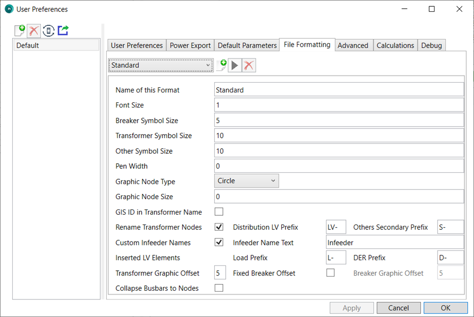
These options control the font size, and the size of breaker and transformer symbols, as well as other symbols within the SINCAL file (eg. infeeders, loads, and transformers). They can also be used to create different groupings of assets within SINCAL, and each grouping can have its own formatting and/or SINCAL object type.
Groupings are set by the drop down at the top of the options. There must always be one grouping, called ‘Standard’, and this grouping cannot be edited. If an asset does not fall into another grouping, or groupings are not used, this will be default option used for formatting and object type. Other groupings can be created by the user through the use of the Create New Grouping button (with the ‘+’ symbol). Once created, other groupings can be edited with the Edit Current Grouping button (the black triangle symbol), or deleted with the Delete Current Grouping button (the red ‘X’). Selecting either the Create New Grouping or Edit Current Grouping buttons will bring up the Grouping Preferences window; please see the help section on that form for more information about that.
Each formatting set has a name (Name of this Format), this is simply the name given to the formatting group to distinguish it from other formatting groups that a user might set up. This name has no impact on what happens within the SINCAL file created by the exporter.
The Pen Width sets the thickness of the lines used when drawing lines and symbols.
Graphic Node Type controls which of the node symbols available in SINCAL is used within the output file. Graphic Node Size controls the size of these symbols. Busbars in SINCAL are automatically detected based on the source system graphical information, and will be drawn as busbars, rather than nodes, so these settings do not normally apply to them.
Other options within this panel control the naming conventions used for certain kinds of elements - whether those names include particular prefixes, and the original ID value from the source system (the name from the source system will always be used, but the ID might also be valuable information in some circumstances). Note that the exporter will also normally place the original ID from the source system within the Master Resources of the element in the output SINCAL file if it is needed.
The Transformer Graphic Offset controls the distance between the nodes of transformers. Since transformers are often created from a single node in the source system, or are created from no graphical information at all in the case of some distribution transformers, the distance between the nodes needs be determined via this setting, rather than from the source information. This distance is also occasionally used to set the distance between other nodes that need separating.
The option Fixed Breaker Offset will determine the availability of the option Breaker Graphic Offset. Normally when creating breakers and protection equipment at terminals, the exporter will do its best to determine a suitable distance to place the terminal equipment away from the node. However, if you would like to manually set this distance, this option exists to allow you to do so. Note that later versions of SINCAL will internally adjust this figure upon loading the SINCAL file, so you may not see the value entered in this field reflected in the SINCAL formatting data. However, the distance should still be set correctly. If the distance is updated through SINCAL, the distance will be updated to match SINCAL’s figure.
The option to Collapse Busbars To Nodes will take busbars (which are normally represented with a horizontal or vertical line), and collapse them to a node (a single point).
Grouping Preferences Form
The grouping preferences form may be accessed through the User Preferences form under the File Formatting tab. Note that the default (“Standard”) grouping may not be edited, and must always exist as a default option for any assets not covered by another grouping.
Groupings do not need to be used, but allow flexibility in the formatting of different assets, through the use of criteria defined by the user and entered through the grouping preferences form. Groupings may also be used to set up different object types within the output SINCAL file. Note that the exporter can only create the object type within the SINCAL file database, the settings of the object type with respect to how items for that object type are formatted are stored within the workspace data, and hence are a part of the .sin file. This can be set within the SINCAL template file. See the section under the User Preferences tab options, or the more detailed information in the FAQ under ‘How can the default settings of the SINCAL file be adjusted?’ for more information about this.
When a grouping is created or edited, its settings are adjusted through the Grouping Preferences window.
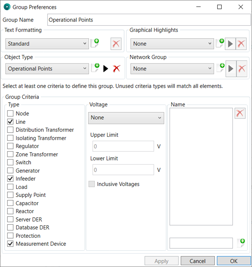
The name given to the group in the Group Name is used to distinguish from other groups that the user might set up. It has no impact on the SINCAL file created by the exporter.
The Text Formatting drop down selects the name of the formatting set that this group should use. If a new formatting set is desired for this group, the user can press the add button to the right of the drop down box. A formatting set can be removed using the delete button to the right of the add button. Note that a formatting set may not be deleted if another group is using the formatting set. The properties of the formatting are controlled on the File Formatting tab of the main user preferences window (ie. The options page that the group preferences are accessed from).
The Graphical Highlights drop down selects the name of any graphical highlights that should be used for nodes belonging to this group. A graphical highlight is a graphical circle placed around nodes belonging to this group. Graphical highlights do not operate for elements. The graphical highlight does not have any impact on the network modelling, but does make certain elements easier to find within the SINCAL file. To avoid overlap, it is recommended to use graphical highlights only for a small number of elements within the SINCAL file. As with the text formatting, graphical highlight sets may be added or removed using the buttons to the right of the drop down. (Graphical highlights may not be removed if other groups are using them). There is also the option to edit an existing set of graphical highlights, using the edit button. Both the add and edit buttons will access a screen allowing the name, colour, radius and thickness of the graphical highlight circle to be controlled.
The Object Type drop down selects the SINCAL object type that should be used for this group. As with the other drop downs, there are buttons to allow the creation or deletion of object types. (Object types may not be removed if other groups are using them). The object type name, and the visibility of the object type within SINCAL may be controlled by through the edit object type button. The annotation settings for the object type within SINCAL can only be set with the SINCAL template (see information earlier in this section).
The Network Group drop down selects the SINCAL Network Element Group that should be created or used for this group. As with the other drop downs, there are buttons to allow the creation or deletion of Network Element Groups. (Network Groups may not be removed if other groups are using them). The network element group name may be controlled through the edit network group button. Setting this drop down to a value other than none will mean that any nodes or elements of this group will set to belong to a network element group of the given name within the created SINCAL file.
The remainder of the window sets the criteria for the group. The criteria define which assets in the SINCAL file belong to the group. At least one criteria must be set for the group to be valid and able to be saved. Unused criteria will not be applied, for example if no voltage criteria is set, then assets of any voltage will be included in the group, so long as they meet the remaining criteria.
The three criteria are asset type, voltage and name. These criteria are generally based on the assets as they appear in EWB or the source data, rather than how they appear in SINCAL. While for the most part this makes little difference, it is a notable consideration for distribution transformers: in SINCAL (for MV only networks), distribution transformers will be modelled as loads, but in EWB they are modelled as transformers. So to have the asset type criteria apply to these, the type should be set to ‘distribution transformer’ rather than ‘load’.
Asset types cover all the types of asset that can be consumed by the exporter, and also include three special cases: ‘Database DER’, ‘Protection’, and ‘Measurement Devices’.
For specific detail on the meaning of the types listed within the type criteria, please see the table below. Some types are translated from the type of DiagramObjectStyle that that they are assigned to within the Energy Workbench (EWB). Documentation for Energy Workbench or the ingestor used for your data can give more detail on how these symbols are set.
| Type Name | Description of Type |
|---|---|
| Node | An asset within the EWB data model from the Junction, BusbarSection or FaultIndicator classes. All EWB ConnectivityNodes will also belong to this category. |
| Line | An asset within the EWB data model from the AcLineSegment class. |
| Distribution Transformer | An asset within the EWB data model from the PowerTransformer class that has its accompanying DiagramObjectStyle set to DIST_TRANSFORMER. |
| Isolating Transformer | An asset within the EWB data from the PowerTransformer table that has its accompanying DiagramObjectStyle set to ISO_TRANSFORMER. |
| Regulator | An asset within the EWB data model from the PowerTransformer class that has its accompanying DiagramObjectStyle set to REVERSIBLE_REGULATOR or NON_REVERSIBLE_REGULATOR. |
| Zone Transformer | An asset within the EWB data model from the PowerTransformer class that has its accompanying DiagramObjectStyle set to ZONE_TRANSFORMER. |
| Switch | An asset within the EWB data model from any possible switch class, ie. Disconnector, LoadBreakSwitch, Recloser, Breaker, Jumper or Fuse. |
| Generator | Available for future, not currently used. |
| Infeeder | An infeeder element created by the SINCAL exporter, to represent the infeed point of the network. Exists immediately upstream of the feeder circuit breaker or zone substation bus, and is equivalent to the (currently unpopulated) EnergySource in the EWB data model. |
| Load | A load element created by the SINCAL exporter, downstream from, or in place of, a distribution transformer. This load type has no direct corresponding element in the EWB database. |
| Supply Point | An asset within the EWB data model from the EnergyConsumer class. |
| Capacitor | An asset within the EWB data model from the LinearShuntCompensator class that is not a reactor (see below). |
| Reactor | An asset within the EWB data model from the LinearShuntCompensator class that has valid information on bPerSection and Sections, with a bPerSection value less than 0. |
| Server DER | An asset within the EWB data model from the PowerElectronicsConnection class. |
| Database DER | Special case [1],[2] |
| Protection | Special case [1],[3] |
| Measurement Device | Special case [1],[4] |
[1] These three types refer to objects created not from data received from the EWB server, but created within the SINCAL exporter itself.
[2] Based on data within either the input database: SINCAL converters contained within the input database on the EmbeddedGeneration table and inserted with the Database DER option on the User Preferences window (User preferences tab), and
[3] Based on data within either the input database: SINCAL protection devices contained within the input database on the ProtectionSettings table and inserted with the Create Protection Devices option on the User Preferences window (advanced tab).
[4] Refers to the measuring devices created when the user elects to use the ‘Create Measuring Devices’ under user preferences.
If no asset types are ticked, this criteria is not considered.
The voltage criteria sets either a maximum voltage, minimum voltage or a range of voltages for the criteria. These limits can be inclusive (ie voltages at the limit value will be considered in the group) or not. If the voltage criteria is set to none, this criteria is not considered.
Finally, the name criteria can limit the group by the name of the asset. Multiple name criteria may be entered, and if an asset name matches any of them, it will meet this criteria. The formatting of the name criteria should follow a Regular Expression pattern, which allows for complex name criteria and wildcard combinations. While regular expressions can be complex to generate they do give a very broad flexibility. Generally a web search for a regular expression matching the pattern desired will give useful results, and there are also testers for regular expressions found online.
If no names are entered, this criteria is not considered.
Advanced
The options on the Advanced tab control the implementation of protection devices, zones, operating points and variants within the output SINCAL file. These are optional additions, which do not need to be used, but which can be set up to provide additional information within the output SINCAL file.
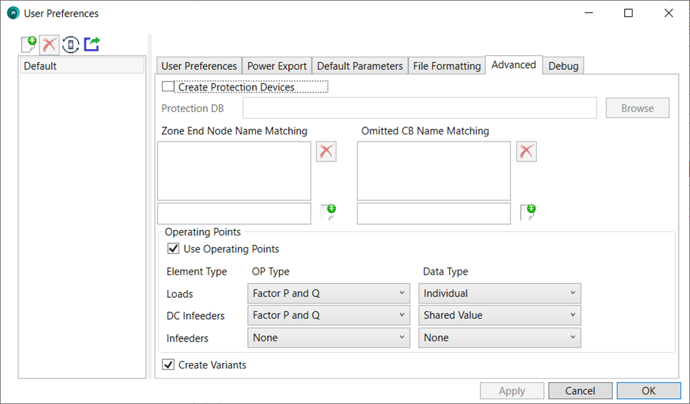 To create protection devices within SINCAL:
-
The input database should contain the appropriate information (see the input database section); and
-
The Create Protection Devices option should be checked; and
-
An appropriate SINCAL Protection database selected; and
-
This Protection database should also be linked within the SINCAL template file (configured under the User Preferences tab).
Once these options are all properly configured, the output SINCAL file should contain the protection elements.
The option Zone End Name Matching allows the exporter to create network zones within the SINCAL file. Network zones will be created by default for each feeder (matching network areas), but can be further subdivided - nodes downstream of node matching the text of one of the entries in this list will be marked as belonging to a new zone. The ends of zones are also used to locate measuring devices, if the option to create measuring devices is selected within the User Preferences section. The names should be written as a regular expression, which is a flexible way of creating pattern matching strings. As an example, consider a case where reclosers in your network data divide the network into different zones that you would like the SINCAL file to recognise. All the reclosers in your network are named with their voltage first (eg. 11, 22, 33, etc), then a dash, and then their type, and then an asset number. So all reclosers would have “-R” as the third and fourth characters of their name. A regular expression could be set to match this with the pattern:
^..-R
This is a very simple pattern, it simply means that from the start of the name (indicated with the “^” character, there are two characters that could be anything (a “.” character is a wildcard match to any character), but the next two characters must be “-R”. Once this is true, the pattern is a match, regardless of anything else in the name.
Much more complex criteria can be created, patterns that match only particular sets of characters, excluding names that have certain letters or patterns, etc. There is a very wide variety of possibilities, which makes it a flexible system. Regular expressions are widely used in other programs, and more information about them can be found online.
As well as being used create the zones themselves, load network element groups are created for each of the zones, containing all of the loads in the zone. This allows for quicker selection and scaling of loads in each zone area.
The Omitted CB Name Matching works in a similar way to the above Zone End Name Matching in terms of how it operates, but in this case if a switch matches the name, it will not be created in the output file. This option allows for fewer switch symbols to appear in the output SINCAL file. This might be desirable where the input data system contains a number of breakers, isolators, earth switches etc that are not needed for the SINCAL model and will just clutter it. The flexible name matching should allow for a variety of filtering as needed.
If Use Operating Points is selected, the exporter will attempt to create operating points in the output SINCAL file. The operating points created will match to those specified in the input database OperatingPoints table. Operating points may be applied to one or more of the types specified within the frame: loads, DC Infeeders (also known as Converters) or Infeeders. The type of Operating Point applied can be selected from the drop-down menu under the OP Type heading. This will correspond to the type of Operating Point that is used within the output SINCAL file. The other drop-down menu, Data Type, will specify the source of the information for the operating points, and how they should be applied. The two options are:
Shared Value: the source of the operating point data will come from the OperatingPointElementData table within the input database. If this option is selected, all elements of this type will share a single operating point.
Individual: the source of the operating point data will come from the OperatingPointIndividualData table within the input database. If this option is selected, each element of this type will have an individual operating point (named after the element). Note that this requires specifying data for each operating point for each individual element within the input database. All the names of these elements (as they exist in the SINCAL file) should be unique for this option to work properly. Duplicate names will result in those elements having incorrect data.
If a default operating point is set in the Input database, this will be applied within the calculation settings under the Network Model / Extended Network model settings within SINCAL, such that this operating point is applied to load flows by default. (This is only applicable for versions 18 and up of SINCAL).
Note that, when using operating points, transformer utilisation information within the source data will be overwritten, and fS, fP and fQ values of loads will be set to 1, regardless of other settings. It is possible to set up an operating point that re-uses this information by creating a default operating point (see the information in the input database configuration about this).
If the option Create Variants is checked, the exporter will create two additional variants within the output SINCAL file: one for a maximum fault level and one for a minimum fault level. The difference between these variants and the base variant will be that the variants will have a different calculation settings value for the Short Circuit Data Type (under the Short Circuit heading within the SINCAL calculation settings). The values will be set according to the name of the variant.
In addition, if both Create Variants and Create Operating Points are checked, one variant will be created for each operating point. Within those operating point variants, for SINCAL versions of at least version 18, the operating point that the variant is named for will be the active operating point under the power flow calculation settings. (Short circuit settings will be left as default). In addition, for operating point variants that are not the default operating point (as defined in the input database settings), switches or breakers at inserted embedded generation (as created when the Database DER option is used) will be closed, rather than open.
Calculations
This tab contains settings for the calculations within the SINCAL Calculation Settings (under Calculate / Settings).
The Load Flow Type and Short Circuit Type will set the corresponding parameters within the SINCAL Calculation Settings.
Network Level Line/Cable Temp. (temperature) will set the value of Overhead Line Temp. (Tline) and Cable Temperature (Tcable) within the Network Level basic data for each network level (also called voltage level) that the SINCAL exporter creates.
The Temp. at End of Short Circuit value sets the field of the same name within the Short Circuit Calculation Settings. It does not set the field of this name (Tend) for each individual line section. Voltage Tolerance will set the value of Voltage Tolerance within the Short Circuit tab for each network level (also called voltage level).
The start time, duration and time step are specified in hours as a decimal (e.g. 14 = 14:00, 14.5 = 14:30, etc.).
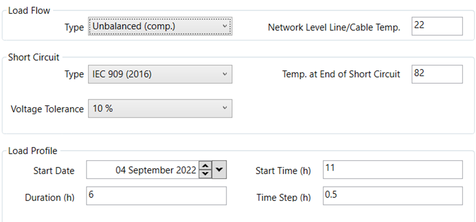 !
The values entered into the Load Control section shown below are simply passed through to the same fields in the SINCAL load flow calculation parameters (under the Load Profile or Time Series headings, depending on your version of SINCAL).
!
The values entered into the Load Control section shown below are simply passed through to the same fields in the SINCAL load flow calculation parameters (under the Load Profile or Time Series headings, depending on your version of SINCAL).
The start date and start time set the first time slot to be used by a load profile study. The start time is specified in hours since midnight, the duration is an inclusive amount of time for the profile to run and the time step indicates the interval between readings.
Debug
The debug tab contains options that might be useful if looking for errors or problems in the exporter or the created SINCAL file.
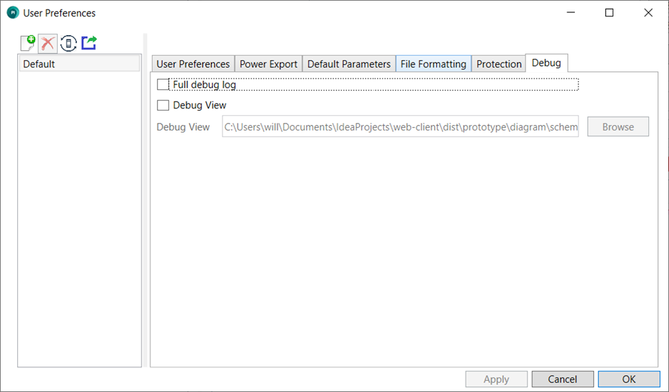
The options for the Full Debug Log and Debug View are intended for use when examining specific issues within an exported file. They will provide more information which may assist in determining the cause of any issues.
Exporting
Once the feeders are selected and the appropriate output options have been configured, the Export button can be pressed, and the export process should start. The log will report progress of the export, and any warnings (orange text) or errors (red text) encountered, as illustrated below.
Once complete, the exported file should be available in the selected location, and you should be able to open it in SINCAL with no further action required.
The log can be accessed with the Show Log button at the bottom of the screen. The log file shows the records from multiple exports, over multiple sessions within the exporter.
The Explore Logs button will open the folder where the log files are stored. Log file sizes are limited, so old logs will be moved to different files as they reach their size limit. Up to 5 old logs of maximum size are stored, once this limit is reached, the oldest log file is removed to make room for the new one.