Exporting Model
As the name suggests, this tool will create SINCAL models for one or more HV feeders, using network data obtained from either a DMS or GIS.
These models are built to be used with the SINCAL smart load integration, or stand alone using nameplate ratings of distribution transformers.
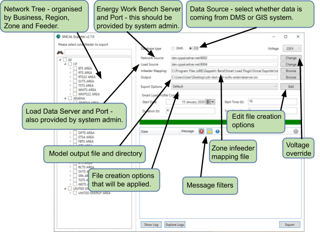
The application should look similar to the image below when it is invoked.
Selecting feeders
Any parts of the HV network can be selected for export. In practical terms, only zones or feeders should be selected. Any more than this, and you may be waiting for a long time for both the model to export, and the model to load and solve in SINCAL.
tip
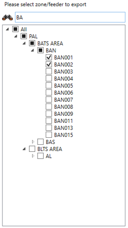
The network tree can be filtered using the search box above the tree.
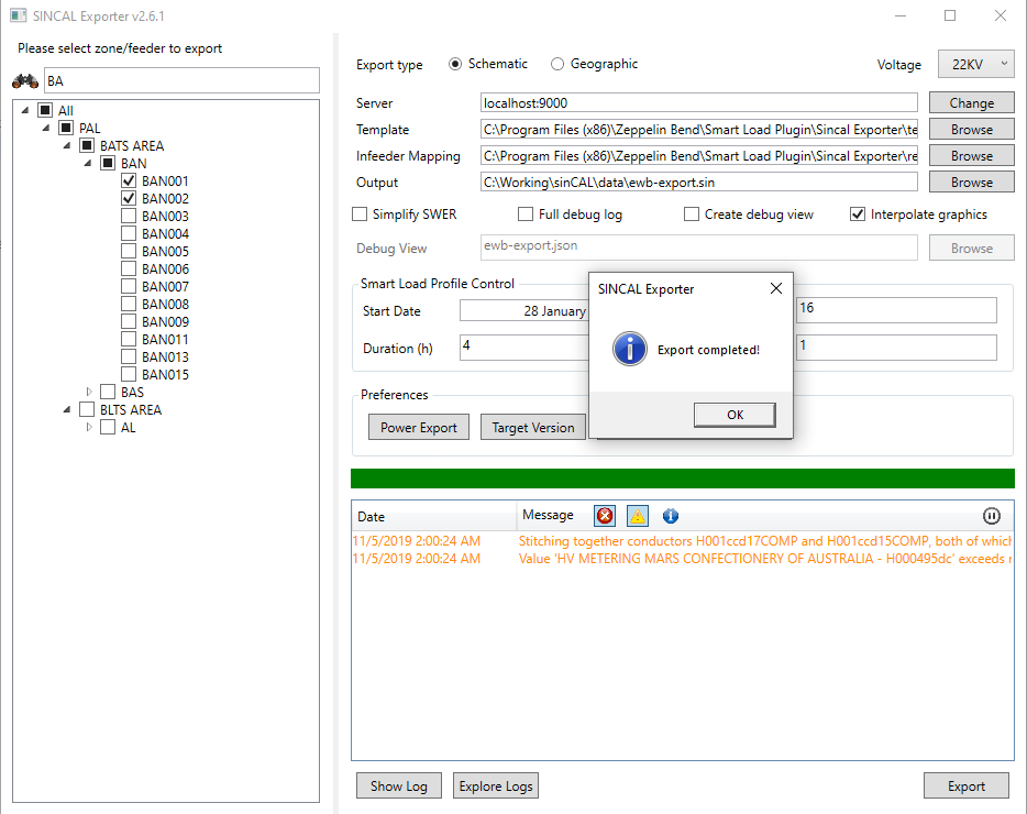
Selecting a network level is done by clicking on or more of the check boxes in the tree, corresponding to a feeder or zone. The display will look something like the following when two feeders under the same Zone are selected for export.
Output Options
Output options are controlled by the options that appear on the main screen (as shown above), which contains options for where data is to be sourced from, and also the settings to be applied for the smart load flow control.
Output options relating to specific options about how the SINCAL file is built from the data may be selected from the Export Options drop down. These options may be created or configured via the Edit button adjacent to the drop down.
Main Form Options
The first output option you will see is the data source type. This is used to select whether the data being exported into SINCAL is sourced from the DMS or the GIS. Differences between these data sources mean that this option should always be set to match the original source system.
Other options on the main form are used to indicate the servers (both for network data and for load data, though these may be the same). Your system administrator should be able to give you this information. The infeeder mapping file contains information about the fault levels (source impedances) for the infeeders within the network. You should supply this information in the correct CSV file format, and indicate where this file is on the system in this field.
The output file is the location where the exporter will create the exported SINCAL file. This can overwrite existing files in that location (though the exporter will give a warning prior to doing this).
The values entered into the Load Control section shown below are simply passed through to the same fields in the SINCAL load flow calculation parameters.

The start date and start time set the first time slot to be used by a smart load profile. The start time is specified in hours since midnight, the duration is an inclusive amount of time for the profile to run and the time step indicates the interval between readings.
info
The start time, duration and time step are specified in hours as a decimal (e.g. 14 = 14:00, 14.5 = 14:30, etc.).
Export Options Form
Using the Edit button on the main form will present all of the detailed options for controlling the export.
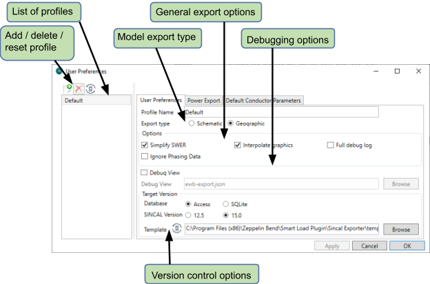
The model export type controls the graphical layout used to generate the SINCAL model. It is only applicable to models sourced from DMS data. If a model is sourced from GIS data, the Geographic export option will automatically be applied. This is due to the availability of graphical data - the GIS system only stores a geographical representation of the network.
If the Simplify SWER option is selected, SWER network (downstream of SWER isolating transformers) will not be included in the model, and a single load will be placed at the location of the isolating transformer, representing the sum of all downstream distribution transformer load.
tip
Using this option, in combination with the Ignore Phasing Data option can generate an entirely balanced network representation if this is needed.
If the Simplify SWER option is not selected, SWER network will be represented within the output file. Please see the section “Using a model†for more information on how this can be used.
Selecting the Interpolate graphics option will make the exporter create graphics for as much of the network as possible. Any node connected to another visible asset will be drawn at the same location. This will potentially cause many nodes to be drawn at the same location, but they can then be relocated manually which is not possible if there are no graphics.
The Ignore Phasing Data option will instruct the exporter to ignore any data on phasing coming from the source information. Instead, all lines and elements will be treated as three phase, unless they are a SWER isolator or in network downstream of a SWER isolator. This option is intended to be used in cases where incorrect phasing data in the source information is leading to problems within the exported file, or where a balanced network is required as the output.
The options for the Full Debug Log and Debug View are intended for use when examining specific issues within an exported file. They will provide more information which may assist in determining the cause of any issues.
The options within the Target Version section will determine the version and type of Sincal database that is created. It also contains the template file that will be used as the basis of exported Sincal files (this template file will include Sincal workspace information, such as annotation and filter data).
Power Export Options
The values used for P and Q can be changed through the options under the Power Export tab on the Export Options form. The various options are explained here.

0 mode
The P and Q values will be 0 for all loads.
Transformer rating mode
The P and Q values will be written using the name plate rating (when available) of the transformer. If name plate rating is not available, the export will use a smart load reading for the load.
![]()
Smart load mode
The P and Q values will be written using the power reading from the server for this distribution transformer at the time specified in the Timestamp field.

tip
Setting the Power Factor to 0 will use the energy reading power factor from EWB.
Default conductor values
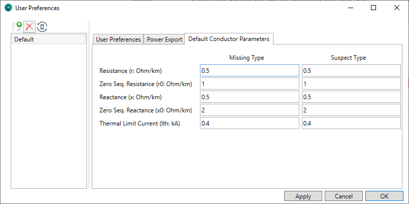
The values used for r, x, r0 and x0 for missing or suspect lines types can be changed in the export tool by accessing the Default Conductor Parameters tab of the Export Options form.
The tab will contain default values for missing and suspect line types, which will be used when dictionary data is not available or appears incorrect. These values are set per profile, so each set of Export Options settings can have their own values.
Exporting
Once the feeders are selected and the appropriate output options have been configured, the Export button can be pressed, and the export process should start. The log will report progress of the export, and any warnings or errors encountered, as illustrated below.
note
For a large rural feeder, this export process should take 30 seconds or less per feeder on a local drive.