This feature is only available to certain customers. If you are interested in using this feature, please contact Zepben for more information.
Interventions Options
This is a reference guide to the different types of interventions available in the Hosting Capacity Module, along with their configuration options and examples.
For an explanation of what interventions are and how they work, including more details on how the Candidate Generation and Allocation process works, please see What are Interventions and how do they work?. For a step-by-step guide to running one, including parent work package requirements and common pitfalls, see How to run an Intervention Work Package.
List of Intervention types
| Intervention Type | Summary |
|---|---|
| LOAD_RESHAPING | Modifies time of use patterns of customer electricity loads by applying load reshape profiles to eligible customers based on targeting criteria. Doesn't simulate tariffs or other programs directly, rather the load shape impact. |
| COMMUNITY_BESS | Installs battery energy storage systems in low-voltage networks to address voltage and thermal constraints caused by high solar penetration or variable loads. Batteries are strategically placed at locations with the most severe network violations. |
| LV_STATCOMS | Deploys Static Synchronous Compensators (STATCOMs) that provide dynamic reactive power compensation to maintain network voltage stability. Responds rapidly to voltage fluctuations, particularly effective for networks with variable loads or distributed generation. |
| DVMS | Implements real-time, automated voltage regulation by continuously adjusting feeder head (zone substation) transformer taps based on customer voltage measurements. Most computationally intensive intervention as it operates at every simulation time step. |
| PHASE_REBALANCING | Redistributes single-phase customers across phases A, B, and C to correct imbalanced phase loading, reducing voltage imbalances and improving network efficiency. |
| DISTRIBUTION_TAP_OPTIMIZATION | Identifies zones with persistent voltage issues and determines optimal annual tap setting changes using heuristic analysis. Unlike DVMS, makes strategic yearly adjustments rather than real-time continuous control. |
| DISTRIBUTION_TX_OLTC | Retrofits distribution transformers with on-load tap changers (OLTCs) to enable dynamic voltage regulation under load conditions, improving voltage quality for downstream customers. |
| THERMAL_LINE_UPGRADE | Reinforces overloaded lines by replacing conductors from the catalogue, prioritised by import/export overload exposure and sized for the configured loading headroom. |
| VOLTAGE_LINE_UPGRADE | Reduces excessive voltage movement by selecting lower-impedance conductor replacements along contributing feeder lines. |
| THERMAL_TRANSFORMER_UPGRADE | Reinforces overloaded transformers with compatible catalogue replacements, prioritised by import/export overload exposure and sized for the configured loading headroom. |
candidateIntervention accepts one of the candidate-based types above except for LOAD_RESHAPING, DVMS, and PHASE_REBALANCING. phaseRebalanceProportions, dvms, and loadReshaping are independent of it and of each other, and can be combined with it in the same work package - see Stacking Interventions.
Intervention Scope
Most candidate-based interventions need only the Network Performance Metrics Enhanced table (populateEnhancedMetrics=True) on the parent work package. All other configurable result tables can be turned off.
| Intervention | Parent tables required |
|---|---|
| COMMUNITY_BESS, LV_STATCOMS, DISTRIBUTION_TX_OLTC, DISTRIBUTION_TAP_OPTIMIZATION | Network Performance Metrics Enhanced |
| THERMAL_LINE_UPGRADE, THERMAL_TRANSFORMER_UPGRADE | Asset Level Thermal Loading Summary (assetLevelSummaries.thermalLoading=True) |
| VOLTAGE_LINE_UPGRADE | Network Performance Metrics Enhanced and Asset Level Voltage Summary (assetLevelSummaries.conductorVoltage=True) |
| LOAD_RESHAPING, DVMS, PHASE_REBALANCING | None read from the parent |
The parent must also be written with writerType=POSTGRES. See Step 1 in How to run an Intervention Work Package.
The Intervention Module works off a reference or parent work package, testing with and without the intervention; candidate-based interventions (candidateIntervention) use the parent work package's Network Performance Metrics Enhanced results to choose which areas to intervene in. For the full set up requirements (contiguous year range, transformer-level measurement zones, matching base/intervention config), see Step 1 in How to run an Intervention Work Package.
Setting up an intervention block
Every intervention work package sets an intervention block of type InterventionConfigInput, pointing parentWorkPackageId at the parent work package, plus one or more of the four intervention blocks below. Any combination can be set on the same work package - see Stacking Interventions. Each type's own section further down has a full worked example.
parentWorkPackageId can also point at another intervention work package rather than a non-intervention work package - this only chains metrics for candidate generation, it does not carry that work package's applied changes forward. See Chaining via parentWorkPackageId.
| Block | Used for |
|---|---|
candidateIntervention | A single candidate-based intervention - COMMUNITY_BESS, LV_STATCOMS, DISTRIBUTION_TX_OLTC, DISTRIBUTION_TAP_OPTIMIZATION, THERMAL_LINE_UPGRADE, VOLTAGE_LINE_UPGRADE or THERMAL_TRANSFORMER_UPGRADE. Only one candidate intervention can be configured per work package. |
phaseRebalanceProportions | PHASE_REBALANCING. |
dvms | DVMS. |
loadReshaping | LOAD_RESHAPING. |
Candidate-based interventions share a common wrapper
Candidate generation queries the parent work package's results directly from the database. A parent written with writerType=PARQUET cannot be used by any of the seven candidate-based types - the intervention will run but find no candidates. Set writerType=POSTGRES on the parent work package.
All seven candidate-based types above are configured the same way, through CandidateInterventionConfigInput:
| Parameter | Description |
|---|---|
interventionType | Required. Which of the seven types to run. |
candidateGeneration | Required. How candidates are identified - its shape depends on interventionType, see that type's own section below for the exact fields. |
candidateAllocationCriteria | Required for COMMUNITY_BESS, LV_STATCOMS and DISTRIBUTION_TX_OLTC only; must be omitted for the others, which allocate directly from candidateGeneration. References an allocation criteria table name. |
allocationInstanceSelection | Optional list of instance or catalogue IDs to restrict candidates to. If omitted, the widest reasonable default is used (see each type's section for specifics). For DISTRIBUTION_TX_OLTC, only the first listed instance is used - list just one to avoid ambiguity. |
yearRange | Optional. Inclusive range of years to search for and apply interventions; omit to use the full range of years in the work package. |
allocationLimitPerYear | Optional. Caps how much gets installed in a single year - see the units note below. Must be greater than 0.0 if set. Defaults to effectively uncapped. |
allocationLimitPerYearFor THERMAL_LINE_UPGRADE and VOLTAGE_LINE_UPGRADE, the limit is in metres of line replaced per year (each candidate's weight is the length of line it replaces). For every other type, the limit is a plain count of interventions per year.
YearRangeInput
| Parameter | Description |
|---|---|
minYear | Required. Earliest year in the candidate search and allocation range, inclusive. |
maxYear | Required. Latest year in the candidate search and allocation range, inclusive, must be >= minYear. |
Any candidateIntervention requires a forecastConfig - it cannot be run from feederConfigs. The asset upgrade types - THERMAL_LINE_UPGRADE, VOLTAGE_LINE_UPGRADE and THERMAL_TRANSFORMER_UPGRADE - additionally require every year in yearRange to also appear in forecastConfig.years, which must itself be non-empty, free of duplicates, and contiguous.
Load Reshaping
Covers use cases such as tariff reform, controlled load hot water programs or other things that shift end user time of use patterns.
Overview
Tables referenced:
- load_reshape_strategies - Defines targeting criteria and application rules. Strategies are applied in order of rank to matching customers (i.e. 1 gets applied first, then 2, etc.). A customer can only receive one load reshape, so once they have been assigned a strategy they are excluded from subsequent strategies. All specified filters must match for a customer to be eligible. NULL/omitted filters are ignored. Some filters will depend on what data is available. This table then references:
- load_reshape_instances - Contains the actual load modification profiles that are applied to customers.
No parent result tables are read by this intervention.
Measuring impact: see How to evaluate an intervention's impact.
Configuration Example
InterventionConfigInput(
    parentWorkPackageId="xxxxxxxx-xxxx-xxxx-xxxx-xxxxxxxxxxxx", # Required
    loadReshaping=LoadReshapingConfigInput(
        loadShapeCriteria="load_reshape_strategy_1"  # References criteria_name in load_reshape_strategies table
    )
)
COMMUNITY_BESS
Community Battery Energy Storage Systems (BESS), also called Neighbourhood BESS, are front-of-the-meter batteries installed in the low-voltage network to mitigate high load and generation issues, especially high solar penetration or very 'spiky' loads. This intervention addresses voltage and thermal constraint violations by strategically deploying batteries at identified problem locations.
Overview
The parent work package needs only the Network Performance Metrics Enhanced table (populateEnhancedMetrics=True). If your intervention_candidate_criteria use thermal hours or event thresholds, also enable the matching calculate...Thermal options in the same config, otherwise those columns are empty. See Step 1 in How to run an Intervention Work Package.
The COMMUNITY_BESS intervention identifies candidate locations where network metrics exceed defined thresholds, then ranks and allocates battery installations based on the severity of constraints.
Tables referenced:
- intervention_candidate_criteria - Defines threshold conditions for identifying problem locations. This table defines the threshold conditions that measurement zones must exceed to qualify as intervention candidates. All specified (non-NULL) thresholds must be met or exceeded (i.e. ≥) for a location to become a candidate.
- intervention_candidates - Stores identified candidates generated as per
intervention_candidate_criteriawith their rankings. Once the list of possible battery candidates has been generated following the rules in the intervention_candidate_criteria table, candidates are ranked based on the severity of constraints, based on the combined sum ofgen_exceeding_normal_thermal_voltage_cecvandload_exceeding_normal_thermal_voltage_vcracross all applicable years. This prioritization ensures that battery installations are targeted to locations with the most significant thermal and voltage issues, maximizing the impact of the intervention. - bess_allocation_criteria - Specifies battery placement and sizing rules (defaults are probably fine and are unlikely to need to be adjusted)
- bess_instances - Contains battery technical specifications and control parameters. Each instance defines a specific battery configuration that can be deployed.
- bess_profiles - Battery operational profiles to use if using
profilecontrol mode, uses the same table as the forecast profiles in non-intervention work packages.
Measuring impact: see How to evaluate an intervention's impact.
Configuration Example
InterventionConfigInput(
    parentWorkPackageId="xxxxxxxx-xxxx-xxxx-xxxx-xxxxxxxxxxxx",  # Required, used to query enhanced metrics
    candidateIntervention=CandidateInterventionConfigInput(
        interventionType=CandidateInterventionClass.COMMUNITY_BESS,
        yearRange=YearRangeInput(minYear=2026, maxYear=2030),  # Optional, defaults to the full range of years in the work package
        allocationLimitPerYear=100,  # Optional. Maximum number of batteries to install per year (not guaranteed to install all 100, as there may be reasons why it can't allocate a certain candidate, e.g. due to phasing)
        candidateGeneration=CandidateGenerationConfigInput(
            type=CandidateGenerationType.CRITERIA,  # Required for COMMUNITY_BESS
            interventionCriteriaName="bess_threshold_set_1",  # References intervention_candidate_criteria.name
            sizingLookaheadYears=3  # Optional, defaults to 0.
        ),
        candidateAllocationCriteria="bess_allocation_criteria_1",  # References bess_allocation_criteria.name
        allocationInstanceSelection=["peakshave_150kw_3ph", "peakshave_100kw_3ph"],    # Optional, pass in a single instance or more than one. If more than 1, they will be sized according to the logic below. If left as null, all available instances in the table will be used for sizing.
    )
)
BESS Sizing
The system automatically selects the battery size for each candidate location using the following process, choosing from the instances passed in via the allocationInstanceSelection parameter, or the full bess_instances table if no list is passed in:
Required kW rating is calculated from thermal metrics
The candidate's required kW rating (min_bess_maxP_kw) is written to the intervention_candidates table during candidate generation, based on the maximum peak instantaneous kW across the first N years, where N is the sizingLookaheadYears, scaled based on the direction of the constraint:
- Load-driven thermal violation:
min_bess_maxP_kw=load_exceeding_normal_thermal_max_kw(from the parent work package network_performance_metrics_enhanced table) - Generation-driven thermal violation:
min_bess_maxP_kw= 0.75 xgen_exceeding_normal_thermal_max_kw(from the parent work package network_performance_metrics_enhanced table)
The 0.75 discount for generation-driven violations reflects that curtailing export is considered less critical than preventing an overload under load conditions. This factor is hardcoded.
Instance is selected from bess_instances
The system selects the most appropriate instance that meets the required capacity (meaning the smallest one that exceeds the minimum size), preferring instances that match the installation year and feeder if those filters are used. The instance's phasing must match the line at the chosen location.
The capacity_scaling_factor (set in bess_allocation_criteria) adds headroom above the calculated requirement. For example, a value of 1.2 means the selected instance must be rated at least 20% above the minimum required kW.
Example: there are 3 sizes in the list: 50kW, 75kW and 100kW. If a specific candidate has a base minimum size of 72kW:
- If
capacity_scaling_factor= 1.0, then the 75kW BESS would be chosen - If
capacity_scaling_factor= 1.2, then the minimum size = 72 x 1.2 = 86.4kW, meaning the 100kW BESS would be chosen.
If the minimum size is larger than any of the available instances, the largest matching one is selected.
If the minimum size is zero, the smallest matching one is selected.
The list is chosen via the allocationInstanceSelection parameter. If this is left out of the config or set to null, then all the instances in the table are chosen from.
If a single instance is given, e.g. allocationInstanceSelection=["standard_BESS"], then that instance will be applied to all suitable locations (it must still match phasing requirements; if not suitable, nothing will be allocated).
If a list of multiple values is given, then the sizing chooses from those, e.g. allocationInstanceSelection=["peakshave_50kw_3ph", "peakshave_100kw_3ph", "peakshave_150kw_3ph"]
BESS Modes
There are 5 valid modes that batteries can operate in, which are the allowable options for control_mode in the bess_instances table:
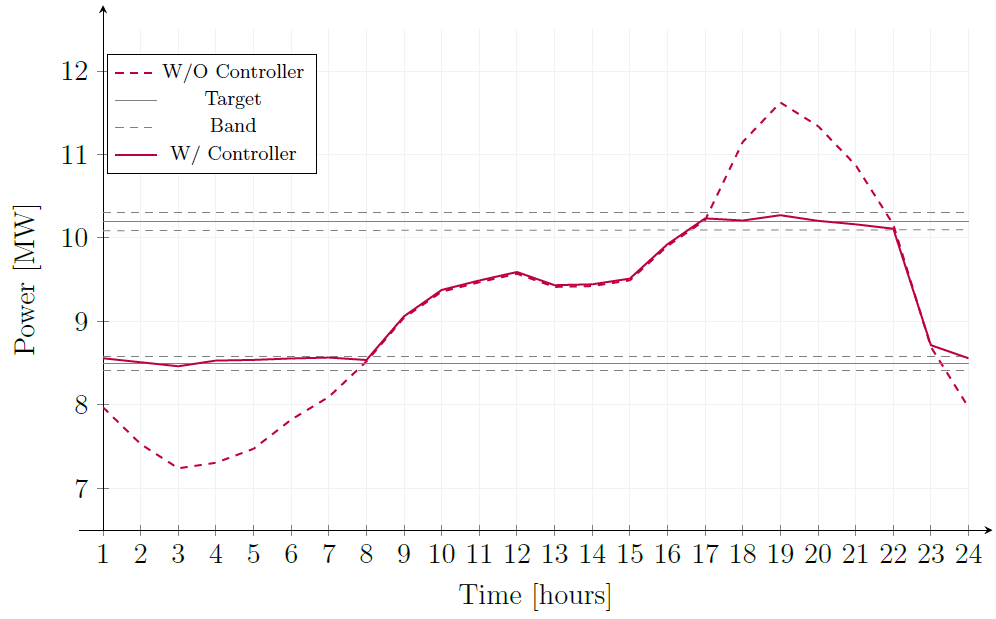
peakshave
Charges when load is low, discharges when load is high. This is measured against the LV transformer for that allocation.
The charge and discharge thresholds are expressed as a percentage of the target asset's kVA rating: the battery charges when the power falls below percentage_rated_kva_target_charging, and discharges when the power rises above percentage_rated_kva_target_discharging (both set in the bess_instances table). The battery will attempt to keep the power at these levels, within the deadband defined by percentage_rated_kva_deadband. This means the battery both fills in the load troughs while charging and shaves the peaks while discharging.
Note that depending on the load conditions on that transformer, there is no guarantee that the battery will cycle properly. If you put the charge threshold at 20%, but the base load on that transformer means it never gets below 30% of its rating, then it will never charge and is thus unable to discharge. Likewise, if the discharge percentage is set at 90%, and it never goes above that, it will never discharge.
Example:
time
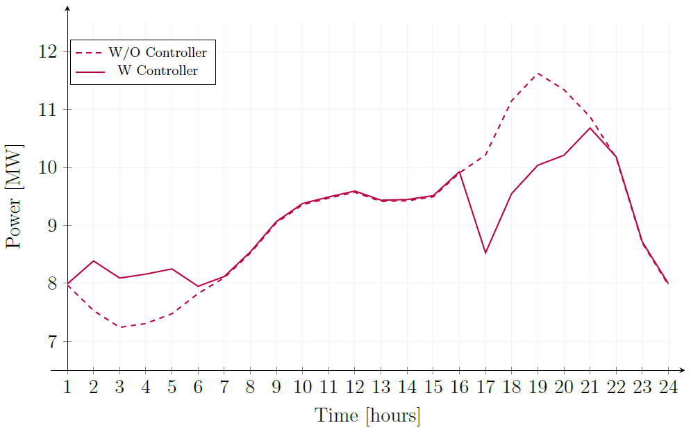
Charges and discharges based on time of day. This mode operates on a fixed schedule, beginning charging and discharging at predetermined times regardless of real-time power conditions. In this mode, the battery will start to charge according to the charge_trigger and start to discharge based on the discharge_trigger parameters. The trigger values are integer values from 0-23 representing the hour of the day (in 24-hour format) when the action should occur. It will charge at the specified charging_rate until full, and discharge at the discharge_rate until empty.
Example:
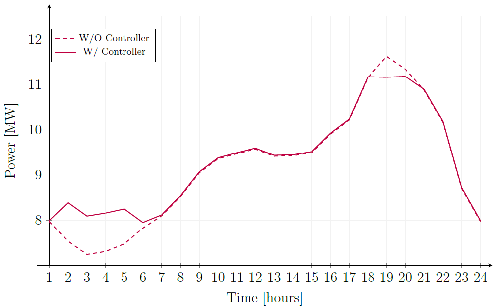
following
For charging, this mode operates just like the time mode.
For discharging, this is similar to peakshave, but the difference is that there is no fixed target value. The target varies according to the power measured at the time specified in discharge_trigger property. Whatever the power level is at the time of discharge will be the target, and the battery will attempt to output within its allowed discharge rate to keep it at that value. In most scenarios, this will typically mean the battery cycles more across a year than in peakshave mode.
Example:
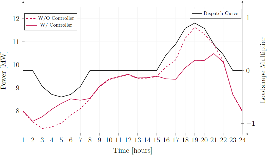
profile
When in this mode, the battery operates according to the profile specified in the profile_id, which links to the corresponding array in the bess_profiles table. That normalised profile will be scaled according to the size of the battery. Note that this does not do any validation on the battery size vs profile values, so it is up to the user to ensure that the profile is suitable for the battery size (i.e. if configured incorrectly, there is nothing stopping a battery from discharging more than its maximum energy storage capacity), and nothing stopping the battery from running at non-ideal times (e.g. charging at times of high demand).
Example:
time_peakshave
This mode is a hybrid of the time and peakshave modes. The battery will charge according to the time-based schedule defined by charge_trigger and charging_rate, but will discharge according to the peakshave logic. Note that the same caveat about setting the discharge % trigger applies as in peakshave mode.
COMMUNITY_BESS units are modelled as OpenDSS storage elements, rather than the Load elements used for scenario-added BESS. This affects how results read:
- OpenDSS energy meters do not count
storageelements as load or generation, so a community battery's own charging and discharging energy is not included inload_kwh,generation_kwh,load_max_kworgen_max_kw, and is not itself counted as energy at risk in the voltage-driven metrics. - The battery's effect on the network is still captured: it changes the flow at the zone head (
peak_import,peak_export, thermal overload) and the zone voltages, and through those voltages it changes the customer energy at risk (VCR, CECV) metrics. - The battery starts the year at 0% state of charge. OpenDSS clamps charge/discharge to what the battery actually has, so an oversized
profilerequest just stops being followed once the battery empties or fills, rather than going negative.
LV_STATCOMS
Low Voltage Static Synchronous Compensators (LV STATCOMs) are voltage regulating devices installed on LV networks to provide dynamic reactive power compensation. These power electronics-based devices act as either a source or sink of reactive AC power, rapidly responding to voltage fluctuations to maintain network stability.
Overview
The parent work package needs only the Network Performance Metrics Enhanced table (populateEnhancedMetrics=True). If your intervention_candidate_criteria use thermal hours or event thresholds, also enable the matching calculate...Thermal options in the same config, otherwise those columns are empty. See Step 1 in How to run an Intervention Work Package.
Candidates are identified where network metrics exceed defined thresholds, then ranked and allocated based on the severity of constraints. Candidates are prioritized by the combined sum of:
gen_exceeding_normal_voltage_cecv(generation causing voltage violations)load_exceeding_normal_voltage_vcr(load causing voltage violations)
This sum is calculated across all applicable years for each candidate location.
Tables referenced:
- intervention_candidate_criteria - Defines threshold conditions for identifying problem locations. All specified (non-NULL) thresholds must be met or exceeded (i.e. ≥) for a location to become a candidate.
- intervention_candidates - Stores identified candidates with their rankings. Candidates are generated based on the criteria specified in
intervention_candidate_criteria. Candidates are ranked by the sum ofgen_exceeding_normal_voltage_cecvandload_exceeding_normal_voltage_vcracross all applicable years - lv_statcom_allocation_criteria - Specifies STATCOM placement rules and network compatibility requirements. The
minimum_x_r_ratiofilter ensures STATCOMs are only deployed where network characteristics allow effective reactive power support. Networks with insufficient inductance (low X/R ratio) may not benefit from STATCOM installation. - lv_statcom_instances - Contains the technical specifications and control parameters for STATCOM devices. Each instance defines a specific STATCOM configuration that can be deployed.
Measuring impact: see How to evaluate an intervention's impact.
Configuration Example
InterventionConfigInput(
    parentWorkPackageId="xxxxxxxx-xxxx-xxxx-xxxx-xxxxxxxxxxxx",  # Required, used to query enhanced metrics
    candidateIntervention=CandidateInterventionConfigInput(
        interventionType=CandidateInterventionClass.LV_STATCOMS,
        yearRange=YearRangeInput(minYear=2026, maxYear=2030),  # Optional, defaults to the full range of years in the work package
        allocationLimitPerYear=100,  # Optional. Maximum number of LV STATCOMs to install per year
        candidateGeneration=CandidateGenerationConfigInput(
            type=CandidateGenerationType.CRITERIA,  # Required for LV_STATCOMS, references intervention_candidate_criteria.name
            # Defines thresholds (e.g., min_voltage_outside_limits_hours), measurement zones meeting or exceeding ALL specified thresholds become candidates
            interventionCriteriaName="threshold_set_2"
        ),
        candidateAllocationCriteria="lv_statcom_allocation_criteria_1",  # References lv_statcom_allocation_criteria.name
        allocationInstanceSelection=["lv_statcom_1ph", "lv_statcom_3ph"],    # Optional: references lv_statcom_instances.name (if not specified, every row in the lv_statcom_instances table is available)
    )
)
Instance selection
Unlike COMMUNITY_BESS, there is no sizing aspect to LV STATCOMs. Instead, the instance is chosen by phasing, after the connection point has been found:
- The connection point is selected first, using
percentage_distance_from_measurement_zone_terminalandminimum_x_r_ratiofromlv_statcom_allocation_criteria. - The number of phases at that connection point is determined.
- From the instances in
allocationInstanceSelection(or the wholelv_statcom_instancestable if omitted), the system picks an instance whosephaseexactly matches the number of phases at the connection point. If there is none, it falls back to an instance with aNULLphase, which is compatible with any phasing. - If no instance matches either way, no LV STATCOM is allocated for that candidate and a warning is logged.
This means a single-phase instance is never installed on a three-phase connection point. To cover a mix of connection points, either pass in a single-phase and a three-phase instance, or use an instance with a NULL phase. There is no year or feeder matching for this type, and if several instances qualify at the same step, there is no guaranteed order between them, so keep the selection to one instance per phasing.
minimum_x_r_ratio
When placing a STATCOM, the system traces the cable path from each downstream energy consumer back to the distribution transformer and accumulates the total reactance (X) and resistance (R) of each segment. For each candidate installation node along that path it computes:
X/R = (total reactance from transformer to node) / (total resistance from transformer to node)
If this ratio does not exceed minimum_x_r_ratio, the STATCOM is not placed at that node.
A STATCOM can only move voltages by sinking or sourcing VArs through the upstream reactance X. If voltage deviations in a network are primarily caused by resistance R (typical of short, resistive LV cable stubs), the STATCOM has little effect. Adjust this threshold to target areas where STATCOMs are best suited to providing voltage support and therefore likely to deliver the greatest value.
Guidance for setting it
| Value | Effect |
|---|---|
NULL or 0.0 | No filter - STATCOM can be placed anywhere regardless of network characteristics. |
~0.3 | Minimum recommended value. Permits STATCOMs at most candidate locations, including areas with predominantly resistive cable. |
~0.5 | Filters out rural or resistive sites where STATCOMs are less efficient, focusing placements on locations where reactive compensation is more effective. |
> 0.5 | Restricts placement to locations where STATCOMs are most effective - areas with higher network inductance where VAr injection has the greatest voltage impact. |
DVMS
Dynamic Voltage Management Systems (DVMS) provide real-time voltage regulation by automatically adjusting feeder head (zone substation) transformer taps based on customer voltage measurements. DVMS only adjusts feeder head taps: distribution transformer taps are not controlled.
Overview
DVMS addresses voltage quality issues through adaptive control of feeder head on-load tap changers (OLTCs). The system continuously monitors customer voltages and adjusts taps to maintain acceptable voltage levels as network conditions change.
Operation:
- Gathers voltage data from multiple customer measurement points downstream of each transformer
- Adjusts feeder head transformer taps at each simulation time step to keep customer voltages within target ranges
- Most computationally intensive intervention - requires solving the network one time step at a time (will add to solving time)
Tables referenced: None - entirely configured via intervention parameters
No parent result tables are read by this intervention.
Any RegControl associated with the Zone Sub is disabled so it cannot affect transformer behaviour. The initial tap position is set to the middle of the tap range, not necessarily a 1.0 p.u. ratio. The first time step is allowed enough iterations to move the tap across the whole range, so the tap normally settles within that step.
Limitations
- Single control point: DVMS only moves the zone substation tap, which shifts the voltage of every customer on the feeder by the same amount. It cannot resolve high voltage at one end of a feeder together with low voltage at the other.
- Count objective, not curtailment: DVMS minimises the number of customer voltage readings outside
lowerLimit/upperLimit. Curtailment is a continuous, energy-weighted measure that ramps up beyond those limits on both the high and low side, so fewer customers outside limits can still mean more curtailment. Several tap positions can give the same count, and DVMS stops at the first one it reaches. - Tap range: DVMS cannot correct voltage once the zone substation tap reaches the end of its range. Tap ranges come from the network model and may not be centred on 1.0 p.u. This is logged at debug level only.
- Regulator settings:
regulatorConfigonly takes effect when control loop 1 makes no tap change attempt in a time step. On feeders with voltage issues this is rare, so changingpuTargetorpuDeadbandPercentoften has little or no effect on results. - HV-only models: if a model has no loads at or below 1 kV, DVMS logs a warning and does not run. The existing zone substation voltage regulation is left in place, so DVMS has no effect on that feeder.
- No inverter response: inverter volt-watt curtailment is not simulated. Curtailment metrics are derived from the resulting voltages, so DVMS affects export indirectly.
For the two-control-loop algorithm DVMS uses to decide tap changes each time step, see How DVMS Control Logic Works.
Measuring impact: see How to evaluate an intervention's impact.
Configuration Example
InterventionConfigInput(
    parentWorkPackageId="xxxxxxxx-xxxx-xxxx-xxxx-xxxxxxxxxxxx",  # Required
    # DVMS applies across all years covered by the work package - there is no separate year range for it
    dvms=DvmsConfigInput(
        # Voltage acceptance criteria
        lowerLimit=0.9,           # Minimum acceptable voltage (per unit)
        upperLimit=1.1,           # Maximum acceptable voltage (per unit)
        lowerPercentile=5,        # Lower percentile of customer voltages to consider (excludes extreme low outliers)
        upperPercentile=95,       # Upper percentile of customer voltages to consider (excludes extreme high outliers)
        maxIterations=3,          # Maximum tap adjustment attempts per time step, after this the solver will move to the next time step regardless of success.
        regulatorConfig=DvmsRegulatorConfigInput(
            puTarget=1.0,                    # Target voltage (per unit)
            puDeadbandPercent=12,           # Deadband width as % of target (e.g., 12 → +/-6% → 0.94-1.06 p.u. with target=1.0)
            maxTapChangePerStep=2,        # Maximum tap positions to change per iteration
            allowPushToLimit=True          # If true, allow tap changes that improve one side of voltage distribution even if worsening the other
        )
    )
)
PHASE_REBALANCING
Phase rebalancing redistributes single-phase customers across phases A, B, and C according to specified proportions to correct uneven phase loading.
Overview
This intervention addresses networks with imbalanced distribution of single-phase customers across the three phases. It reallocates customers to achieve a more balanced load distribution, reducing phase voltage imbalances and improving network efficiency.
Note that this intervention considers customers one by one and can be limited by what phases are available at a given location, so the actual achieved proportions may differ from the target proportions specified in the intervention parameters, especially in network areas with large spurs all on a single phase. Also note that this intervention targets customer count, not load, so even a perfect balance of customers may not result in a perfect balance of load across phases.
Tables referenced: None - entirely configured via intervention parameters
No parent result tables are read by this intervention.
Measuring impact: see How to evaluate an intervention's impact.
Configuration Example
InterventionConfigInput(
    parentWorkPackageId="xxxxxxxx-xxxx-xxxx-xxxx-xxxxxxxxxxxx",  # Required
    # Phase rebalancing applies across all years covered by the work package - there is no separate year range for it
    phaseRebalanceProportions=PhaseRebalanceProportionsInput(
        # Target proportions for redistributing single-phase customers
        # Values do not need to sum to 1 (they are normalized internally), but all values must be non-negative and at least one must be > 0
        # For even distribution, use: a=1, b=1, c=1
        a=0.25,  # 25% of customers allocated to phase A
        b=0.35,  # 35% of customers allocated to phase B
        c=0.4    # 40% of customers allocated to phase C
    )
)
DISTRIBUTION_TAP_OPTIMIZATION
Distribution tap optimization identifies measurement zones with persistent voltage compliance issues and recommends static distribution transformer tap setting changes on an annual basis using heuristic analysis of voltage statistics from the parent work package.
Overview
The parent work package needs only the Network Performance Metrics Enhanced table (populateEnhancedMetrics=True). See Step 1 in How to run an Intervention Work Package.
Key differences from DVMS
- Tap settings change at most once per transformer per year, not every time step.
- Not a real-time feedback system - candidates are generated from parent work package results.
- Significantly less computationally intensive.
Tables referenced:
Candidate selection happens via the config values, NOT the intervention_candidate_criteria table. Candidates are stored in the intervention_candidates table.
Applicability and annual allocation Tap optimization is designed to be applicable to all distribution transformers by default (static improvements to persistent bias).
Unlike criteria-based interventions (COMMUNITY_BESS, LV_STATCOMS, DISTRIBUTION_TX_OLTC) where a candidate spans the full year range, each tap optimization candidate covers a single transformer in a single year. Tap positions are re-evaluated independently per simulation year, so the same transformer may be a candidate in multiple years with different recommended tap settings.
To approximate operational restrictions (i.e. a works program that has budget to modify only X transformers per year), the intervention can be capped using allocationLimitPerYear.
When a cap is applied, candidates are ranked by the p.u. deviation of the worst-case voltage percentile from nominal (1.0 p.u.) - V1 for boost candidates and V99 for buck candidates (defined below). The candidate with the greatest deviation ranks first.
Measuring impact: see How to evaluate an intervention's impact.
Configuration example
InterventionConfigInput(
    parentWorkPackageId="xxxxxxxx-xxxx-xxxx-xxxx-xxxxxxxxxxxx", # Required, used to query voltage metrics from base scenario
    candidateIntervention=CandidateInterventionConfigInput(
        interventionType=CandidateInterventionClass.DISTRIBUTION_TAP_OPTIMIZATION,
        yearRange=YearRangeInput(minYear=2026, maxYear=2030),  # Optional, defaults to the full range of years in the work package
        allocationLimitPerYear=100, # Optional, leave out to apply to an unlimited number of transformers per year
        candidateGeneration=CandidateGenerationConfigInput(
            type=CandidateGenerationType.TAP_OPTIMIZATION, # Required for DISTRIBUTION_TAP_OPTIMIZATION

            # Voltage thresholds (applied per measurement zone per year)
            averageVoltageSpreadThreshold=40,
            voltageUnderLimitHoursThreshold=48,
            voltageOverLimitHoursThreshold=48,
            # (these metrics are explained below)

            # Tap weighting thresholds (direction arbitration)
            # Default values (-10.0, 10.0) are suitable for most cases
            tapWeightingFactorLowerThreshold=-10.0,
            tapWeightingFactorUpperThreshold=10.0
        )
    )
)
Key metrics and parameters
voltage_delta_avg (metric)
The average voltage range across nodes in the measurement zone, pooled across phases and timesteps over the relevant time period (not the worst-case phase per timestep — all phases are pooled together).
Average(phv.phs1.max - phv.phs1.min, phv.phs2.max - phv.phs2.min, phv.phs3.max - phv.phs3.min) pooled over all phases and timesteps
Higher values indicate larger typical voltage spread between nodes (weak networks, long runs, or phase imbalance). Note: voltage_delta_avg is in p.u. but is converted to volts for comparison with averageVoltageSpreadThreshold.
averageVoltageSpreadThreshold (swing gating)
When voltage_delta_avg (in volts) exceeds this threshold, the network has significant spatial voltage spread and the algorithm restricts itself to 1-step tap changes. Below it, 2-step changes may be recommended for clearly high or low voltage regimes. Specify in phase-to-phase volts (e.g. 40 = 40V = 10% of 400V nominal).
Persistence thresholds: voltageUnderLimitHoursThreshold and voltageOverLimitHoursThreshold
Minimum annual hours of under/overvoltage before the algorithm treats an issue as persistent enough to justify a tap change. Defaults have been tuned to avoid acting on short-lived or non-representative excursions.
voltageUnderLimitHoursThreshold: minimum hours below the lower voltage boundvoltageOverLimitHoursThreshold: minimum hours above the upper voltage bound
V1_avg and V99_avg (voltage distribution inputs)
V1_avg is the 1st percentile and V99_avg is the 99th percentile of average node voltages across the measurement zone in p.u. They characterise the low and high tails of the annual voltage distribution: V1_avg represents typical worst-case undervoltage conditions; V99_avg represents typical worst-case overvoltage conditions. Both are used throughout the decision logic and ranking below.
Direction arbitration: tapWeightingFactorLowerThreshold & tapWeightingFactorUpperThreshold
When both hour thresholds are exceeded, a weighting factor determines which side dominates before a direction is recommended:
tapWeightingFactor = (|V99_avg - 1.0| * hours_over_limit) - (|V1_avg - 1.0| * hours_under_limit)
- Positive (overvoltage dominates): if >
tapWeightingFactorUpperThreshold→ buck candidate - Negative (undervoltage dominates): if <
tapWeightingFactorLowerThreshold→ boost candidate - Within the deadband: no tap change recommended
This prevents small offsetting exceedances from driving tap changes that improve one voltage tail while worsening the other.
The directional p.u. thresholds within the decision logic (1.1, 0.94, 0.91, 1.075) are fixed and not user-configurable. Only the four parameters above (averageVoltageSpreadThreshold, voltageUnderLimitHoursThreshold, voltageOverLimitHoursThreshold, and the tap weighting factor thresholds) can be tuned.
For the exact case-by-case decision logic and candidate ranking, see How Distribution Tap Optimization Decides Tap Changes.
DISTRIBUTION_TX_OLTC
Distribution Transformer On-Load Tap Changers (OLTC) enable voltage regulation at distribution transformers by allowing tap position changes under load conditions, without interrupting power supply.
Overview
The parent work package needs only the Network Performance Metrics Enhanced table (populateEnhancedMetrics=True). If your intervention_candidate_criteria use thermal hours or event thresholds, also enable the matching calculate...Thermal options in the same config, otherwise those columns are empty. See Step 1 in How to run an Intervention Work Package.
This intervention retrofits existing distribution transformers with on-load tap changing capability, allowing dynamic voltage control to address network voltage issues. OLTCs provide automated tap adjustment in response to network conditions, improving voltage quality for downstream customers.
Candidates are identified where network metrics exceed defined thresholds, then ranked and allocated based on the severity of constraints. Candidates are prioritized by the combined sum of:
gen_exceeding_normal_voltage_cecv(generation causing voltage violations)load_exceeding_normal_voltage_vcr(load causing voltage violations)
This sum is calculated across all applicable years for each candidate location.
Tables referenced:
- intervention_candidate_criteria - Defines threshold conditions for identifying problem locations. All specified (non-NULL) thresholds must be met or exceeded (i.e. ≥) for a location to become a candidate.
- intervention_candidates - Stores identified candidates with their rankings.
- distribution_transformer_oltc_allocation_criteria - Specifies OLTC installation rules and requirements
- distribution_transformer_oltc_instances - Contains OLTC technical specifications and control parameters. Each instance defines a specific OLTC configuration that can be deployed.
Measuring impact: see How to evaluate an intervention's impact.
Configuration Example
InterventionConfigInput(
    parentWorkPackageId="xxxxxxxx-xxxx-xxxx-xxxx-xxxxxxxxxxxx",  # Required, used to query enhanced metrics
    candidateIntervention=CandidateInterventionConfigInput(
        interventionType=CandidateInterventionClass.DISTRIBUTION_TX_OLTC,
        yearRange=YearRangeInput(
            minYear=2026,  # Earliest year to identify and apply intervention candidates
            maxYear=2030   # Latest year to identify and apply intervention candidates
        ),  # Optional, defaults to the full range of years in the work package
        allocationLimitPerYear=100,  # Optional. Maximum number of OLTCs to install per year
        candidateGeneration=CandidateGenerationConfigInput(
            type=CandidateGenerationType.CRITERIA,  # Required for DISTRIBUTION_TX_OLTC
            # References intervention_candidate_criteria.name
            # Defines thresholds (e.g., min_voltage_outside_limits_hours)
            # Measurement zones meeting or exceeding ALL specified thresholds become candidates
            interventionCriteriaName="threshold_set_2"
        ),
        candidateAllocationCriteria="distribution_transformer_oltc_allocation_criteria_1",  # References distribution_transformer_oltc_allocation_criteria.name
        allocationInstanceSelection=["distribution_transformer_oltc_instance_1"],    # Optional: references distribution_transformer_oltc_instances.name
                                                                                     # Only the first listed instance is used - list just one to avoid ambiguity
                                                                                     # If omitted, the first row in the table is used - no guaranteed order, so specify an instance explicitly
    )
)
THERMAL_LINE_UPGRADE
Thermal line upgrade replaces overloaded line segments with a conductor catalogue entry that has enough current rating to bring the line loading back to the configured target loading percentage.
For why you'd use this intervention and its expected impact, see THERMAL_LINE_UPGRADE in Interventions Concepts.
Overview
The parent work package needs the Asset Level Thermal Loading Summary table (assetLevelSummaries.thermalLoading=True), which is off by default. Other configurable result tables can be off. See Step 1 in How to run an Intervention Work Package.
This intervention is generated from asset-level thermal loading summaries in the parent work package. It does not use intervention_candidate_criteria or a separate allocation criteria table. Candidate generation finds simplified OpenDSS line assets with hours_over_normal > 0, maps them back to the original CIM AcLineSegment assets, calculates the required replacement current rating, ranks the candidates, then allocation applies a matching row from conductor_catalog.
The parent work package must have been run with assetLevelSummaries.thermalLoading=True, which is off by default. Without it asset_level_thermal_loading_summary is empty, no candidates are generated, and the intervention work package completes successfully having applied nothing.
Candidates are grouped by feeder and simplified line mRID. If a simplified line maps to multiple original CIM line segments, all mapped original lines are upgraded together as one candidate.
Candidates are ranked by:
score = importValue * overload_kwh_import + exportValue * overload_kwh_export
importValue and exportValue are relative weights (not currency or percentages) that let you decide whether load-driven overloads, export-driven overloads, or both should drive prioritisation - they don't change the required rating for an individual candidate. A candidate with a score of 0.0 or less is not generated, so at least one of the two must be greater than 0.0. Defaults: importValue=1.0, exportValue=0.1, targetLoadingPct=80.0.
The required conductor current rating is calculated from the peak current observed after the first overloaded year:
required_rating = max_current / (targetLoadingPct / 100.0)
For example, if a line reaches 220 A and targetLoadingPct is 80.0, the selected conductor must be rated at least 275 A. Lower targetLoadingPct values create more headroom but require larger catalogue entries.
Setting it lower does not mean more upgrades. Because the required rating scales as 1 / targetLoadingPct, halving the target roughly doubles the conductor size each candidate needs. The candidate list itself does not change - targetLoadingPct affects sizing, not which assets are selected - but candidates that had a viable catalogue row at the default may have none at a stricter setting, and are then skipped without an error. How pronounced that is depends entirely on how far your catalogue extends above present-day ratings.
| Value | Effect |
|---|---|
> 80.0 | Sizes replacements close to the observed peak. More candidates find a viable conductor, but with lower headroom for further load growth. |
80.0 | Default. A reasonable balance between headroom and catalogue availability on most networks. |
< 80.0 | More headroom per upgrade, but larger replacements. Expect fewer candidates to allocate unless the catalogue extends well above present-day ratings. |
If a lower target is what you want for planning reasons, check the gap between intervention_candidates and applied_line_upgrade before concluding the network needs less work than it does.
Tables referenced:
- asset_level_thermal_loading_summary - Source results table used to identify overloaded line assets and calculate overload energy, maximum loading, and required rating.
- cim_to_opendss - Maps simplified OpenDSS lines back to the original CIM
AcLineSegmentmRIDs that will be upgraded. - intervention_candidates - Stores the generated candidate rows, including ranking, target original mRIDs, score, required rating, and line length.
- conductor_catalog - Selectable replacement conductor catalogue.
allocationInstanceSelectionfilters this table byidwhen supplied. - applied_line_upgrade - Output table containing the actual line upgrade allocations that were applied.
Measuring impact: see How to evaluate an intervention's impact.
Configuration Example
InterventionConfigInput(
    parentWorkPackageId="xxxxxxxx-xxxx-xxxx-xxxx-xxxxxxxxxxxx",  # Required, used to query asset-level thermal results
    candidateIntervention=CandidateInterventionConfigInput(
        interventionType=CandidateInterventionClass.THERMAL_LINE_UPGRADE,
        yearRange=YearRangeInput(
            minYear=2026,
            maxYear=2030
        ),  # Optional. Every year in the range must also be in forecastConfig.years, so either
            # match it to your own work package or omit it to use the full range.
        allocationLimitPerYear=5000.0,  # Optional. Maximum metres of line to upgrade per year
        candidateGeneration=CandidateGenerationConfigInput(
            type=CandidateGenerationType.THERMAL_LINE_UPGRADE,
            importValue=1.0,        # Optional, defaults to 1.0
            exportValue=0.1,        # Optional, defaults to 0.1
            targetLoadingPct=80.0   # Optional, defaults to 80.0
        )
        # allocationInstanceSelection omitted, so every conductor_catalog row is considered.
        # Only set it once you know which catalogue IDs you want to restrict to - a selection
        # that excludes the ratings your overloaded lines need will leave candidates unallocated.
    )
)
Don't set candidateAllocationCriteria for this intervention. The yearly allocation limit and years are taken from allocationLimitPerYear and yearRange.
Candidate Selection and Allocation
A thermal line upgrade candidate is generated only when all of the following are true:
- The parent work package has an
asset_level_thermal_loading_summaryrow for a simplified line asset in the selected scenario, feeder, and year range. - The asset has
hours_over_normal > 0. - The simplified line maps through
cim_to_opendssto at least one original CIMAcLineSegment. max_currentis available, so a required conductor rating can be calculated.- The weighted import/export overload score is greater than
0.0.
Allocation then selects the smallest viable conductor catalogue row for each target original line. A conductor is viable when it:
- Has
rated_current >= required_rating. - Matches the line voltage, either by
applicable_base_voltages_vor byvoltage_level. - Supports the line phase count and neutral requirement.
- Has the same
wire_info_classas the existing line:OverheadWireInfofor overhead lines andCableInfofor underground lines. - Does not increase the line positive-sequence impedance magnitude.
If a collapsed candidate maps to multiple original line segments, the same conductor catalogue row must be viable for every segment. If different target segments would choose different catalogue rows, no allocation is produced for that candidate.
allocationLimitPerYear is measured in metres for this intervention. Each candidate's weight is the combined length of the target original line segments (total_length_m).
THERMAL_TRANSFORMER_UPGRADE
Thermal transformer upgrade replaces overloaded transformers with a transformer catalogue entry sized to bring the transformer loading back to the configured target loading percentage.
For why you'd use this intervention and its expected impact, see THERMAL_TRANSFORMER_UPGRADE in Interventions Concepts.
Overview
The parent work package needs the Asset Level Thermal Loading Summary table (assetLevelSummaries.thermalLoading=True), which is off by default. Other configurable result tables can be off. See Step 1 in How to run an Intervention Work Package.
This intervention is generated from asset-level thermal loading summaries in the parent work package. It does not use intervention_candidate_criteria or a separate allocation criteria table. Candidate generation finds simplified OpenDSS transformer assets with hours_over_normal > 0, calculates the required replacement kVA, ranks the candidates, then allocation applies a matching row from transformer_catalog.
The parent work package must have been run with assetLevelSummaries.thermalLoading=True, which is off by default. Without it asset_level_thermal_loading_summary is empty, no candidates are generated, and the intervention work package completes successfully having applied nothing.
Candidates are grouped by feeder and transformer mRID. They are ranked by the same weighted overload-energy score used for thermal line upgrades - see THERMAL_LINE_UPGRADE above for the formula and importValue/exportValue defaults.
The required transformer rating is calculated from the peak loading observed after the first overloaded year:
peak_loading_kva = normal_rating * max_loading_pct / 100.0
required_kva = peak_loading_kva / (targetLoadingPct / 100.0)
For example, if a 500 kVA transformer reaches 120% loading and targetLoadingPct is 80.0, the selected replacement must be rated at least 750 kVA.
As with thermal line upgrades, lowering targetLoadingPct raises the required rating and so makes a viable catalogue row less likely - see the note under THERMAL_LINE_UPGRADE. Transformer catalogues tend to be less exposed to this than conductor catalogues, since standard transformer sizes step up well beyond typical present-day loading, but the same check applies: compare intervention_candidates against applied_transformer_upgrade if fewer upgrades land than expected.
Tables referenced:
- asset_level_thermal_loading_summary - Source results table used to identify overloaded transformer assets and calculate overload energy, peak loading, and required kVA.
- cim_to_opendss - Used to confirm that the overloaded asset is a simplified
PowerTransformer. - intervention_candidates - Stores the generated candidate rows, including ranking, score, required kVA, and peak loading.
- transformer_catalog - Selectable replacement transformer catalogue.
allocationInstanceSelectionfilters this table byidwhen supplied. - applied_transformer_upgrade - Output table containing the actual transformer upgrade allocations that were applied.
Measuring impact: see How to evaluate an intervention's impact.
Configuration Example
InterventionConfigInput(
    parentWorkPackageId="xxxxxxxx-xxxx-xxxx-xxxx-xxxxxxxxxxxx",  # Required, used to query asset-level thermal results
    candidateIntervention=CandidateInterventionConfigInput(
        interventionType=CandidateInterventionClass.THERMAL_TRANSFORMER_UPGRADE,
        yearRange=YearRangeInput(
            minYear=2026,
            maxYear=2030
        ),  # Optional. Every year in the range must also be in forecastConfig.years, so either
            # match it to your own work package or omit it to use the full range.
        allocationLimitPerYear=25,  # Optional. Maximum number of transformers to upgrade per year
        candidateGeneration=CandidateGenerationConfigInput(
            type=CandidateGenerationType.THERMAL_TRANSFORMER_UPGRADE,
            importValue=1.0,        # Optional, defaults to 1.0
            exportValue=0.1,        # Optional, defaults to 0.1
            targetLoadingPct=80.0   # Optional, defaults to 80.0
        )
        # allocationInstanceSelection omitted, so every transformer_catalog row is considered.
        # Restricting to a couple of standard sizes is reasonable once you know the catalogue,
        # but a selection that excludes the ratings you need will leave candidates unallocated.
    )
)
Don't set candidateAllocationCriteria for this intervention. The yearly allocation limit and years are taken from allocationLimitPerYear and yearRange.
Candidate Selection and Allocation
A thermal transformer upgrade candidate is generated only when all of the following are true:
- The parent work package has an
asset_level_thermal_loading_summaryrow for a simplified transformer asset in the selected scenario, feeder, and year range. - The asset has
hours_over_normal > 0. - The asset is mapped as a simplified
PowerTransformer. - The weighted import/export overload score is greater than
0.0.
Allocation selects the smallest viable transformer catalogue row. A transformer is viable when it:
- Has
rated_kva >= required_kva. - Matches the existing primary and secondary voltage, either by the applicable base-voltage lists or by the primary and secondary voltage-level fields.
- Supports the existing primary and secondary phase codes.
- Has the same transformer function kind as the existing transformer.
- Preferably has the same construction kind as the existing transformer. If no construction-matching row is viable, allocation falls back to rows that match the other requirements but not construction kind.
allocationLimitPerYear is a count for this intervention. Each candidate has a weight of 1.0.
VOLTAGE_LINE_UPGRADE
Voltage line upgrade replaces line segments to reduce voltage swing issues around transformer measurement zones. It uses asset-level voltage summaries to identify lines that contribute to voltage movement, then chooses lower-impedance conductor catalogue rows that are expected to capture the most voltage value per metre upgraded.
For why you'd use this intervention and its expected impact, see VOLTAGE_LINE_UPGRADE in Interventions Concepts.
Overview
The parent work package needs both the Network Performance Metrics Enhanced table (populateEnhancedMetrics=True) and the Asset Level Voltage Summary table (assetLevelSummaries.conductorVoltage=True, off by default). Other configurable result tables can be off. See Step 1 in How to run an Intervention Work Package.
This intervention is generated from transformer-level enhanced metrics and asset-level voltage summaries in the parent work package. It does not use intervention_candidate_criteria or a separate allocation criteria table.
The parent work package must have been run with assetLevelSummaries.conductorVoltage=True, which is off by default. Without it asset_level_voltage_summary is empty, no candidates are generated, and the intervention work package completes successfully having applied nothing.
Candidate generation starts with transformer measurement zones that have voltage issues. A transformer zone is eligible in a year when:
- It is a transformer measurement zone.
- It has
maximum_section_voltageandminimum_section_voltage. - The sum of
load_exceeding_normal_thermal_voltage_vcrandgen_exceeding_normal_thermal_voltage_cecvis greater than0.0. - Either its voltage swing exceeds
targetVoltageSwingPu, or its maximum voltage delta exceedsvoltageDeltaThresholdPu.
The required correction for that transformer-zone year is:
All voltage values in this calculation are per-unit values on the measurement zone's voltage base. Multiply them by v_base only when converting the result for display in volts; compare them directly with the p.u. configuration values.
required_correction_pu = max(
    maximum_section_voltage - minimum_section_voltage - targetVoltageSwingPu,
    voltage_delta_max - voltageDeltaThresholdPu,
    0.0
)
The generator then traces upstream lines from the transformer and downstream lines in the transformer's LV feeder. It maps those original CIM line mRIDs to simplified OpenDSS line assets, reads their asset_level_voltage_summary.avg_abs_delta, and attributes the transformer-zone value across related lines in proportion to each line's average absolute voltage delta.
Candidates are grouped by feeder and simplified line mRID. If a simplified line maps to multiple original CIM line segments, all mapped original lines are upgraded together as one candidate.
Tables referenced:
- network_performance_metrics_enhanced - Source table used to find transformer measurement zones with voltage swing or voltage-delta issues.
- asset_level_voltage_summary - Source table used to estimate how strongly each related line contributes to voltage movement.
- cim_to_opendss - Maps original CIM
AcLineSegmentassets to simplified OpenDSS line assets and back to the original line mRIDs that will be upgraded. - intervention_candidates - Stores the generated candidate rows, including target original mRIDs, recommended conductor, captured value, value per metre, and measurement-zone breakdown.
- conductor_catalog - Selectable replacement conductor catalogue.
allocationInstanceSelectionfilters this table byidduring candidate generation when supplied. - applied_line_upgrade - Output table containing the actual line upgrade allocations that were applied.
Measuring impact: see How to evaluate an intervention's impact.
Configuration Example
InterventionConfigInput(
    parentWorkPackageId="xxxxxxxx-xxxx-xxxx-xxxx-xxxxxxxxxxxx",  # Required, used to query voltage metrics and asset-level voltage results
    candidateIntervention=CandidateInterventionConfigInput(
        interventionType=CandidateInterventionClass.VOLTAGE_LINE_UPGRADE,
        yearRange=YearRangeInput(
            minYear=2026,
            maxYear=2030
        ),  # Optional. Every year in the range must also be in forecastConfig.years, so either
            # match it to your own work package or omit it to use the full range.
        allocationLimitPerYear=999000.0,  # Optional. Maximum metres of line to upgrade per year
        candidateGeneration=CandidateGenerationConfigInput(
            type=CandidateGenerationType.VOLTAGE_LINE_UPGRADE,
            targetVoltageSwingPu=0.16,             # Optional, defaults to 0.16
            voltageDeltaThresholdPu=0.08,          # Optional, defaults to 0.08
            upstreamEffectivenessFactor=1.0,       # Optional, defaults to 1.0
            internalMzEffectivenessFactor=0.5,     # Optional, defaults to 0.5
            defaultUpgradeReductionFactor=0.6,     # Optional, defaults to 0.6
            targetHeadroomFactor=1.1,              # Optional, defaults to 1.1
            minLineLengthM=5.0,                    # Optional, defaults to 5.0
            minAvgAbsDeltaPu=0.001                 # Optional, defaults to 0.001
        )
        # allocationInstanceSelection omitted, so every conductor_catalog row is considered.
        # This intervention needs lower-impedance options to choose from, so restricting the
        # catalogue here is more likely to leave candidates without a viable conductor than it
        # is for the thermal types.
    )
)
Voltage line upgrade configuration
This configuration controls which voltage issues qualify, how candidate line influence is estimated, which conductor options are available, and how much work can be applied each year.
Set both interventionType and candidateGeneration.type to VOLTAGE_LINE_UPGRADE. These select the voltage-line candidate-generation logic. candidateAllocationCriteria is not used and should be omitted.
Voltage thresholds and movement values are expressed in per-unit (p.u.) on the relevant measurement-zone voltage base.
| Configuration item | Why you might change it | Impact of the setting |
|---|---|---|
parentWorkPackageId | Select the parent work package whose measurement-zone and line-voltage results should drive the upgrade plan. | Changing the parent changes eligible zones, contributing lines, candidate values, and selected conductors. Keep the parent and intervention work packages otherwise comparable when measuring benefit. |
yearRange | Focus the reinforcement plan on particular forecast years. | Candidates are searched for and applied only within the inclusive range. For asset upgrades, every selected year must also exist in forecastConfig.years. |
allocationLimitPerYear | Represent the amount of line length that can be designed, procured, or constructed in one year. | The limit applies to the combined length of the original lines in each candidate. Lower limits can defer lower-ranked work to later years. |
allocationInstanceSelection | Restrict replacements to approved conductor catalogue IDs, such as standard low-impedance overhead or cable designs. | Only the selected catalogue rows are considered. A narrow selection may leave an otherwise eligible candidate without a viable conductor. If omitted, all catalogue rows are considered. |
targetVoltageSwingPu | Set the maximum preferred difference between the highest and lowest section voltage in a transformer measurement zone. | Lower values are stricter and require more correction, generally meaning a greater impedance reduction. A candidate may be dropped if no selected conductor can meet the target. |
voltageDeltaThresholdPu | Set an additional threshold for deciding whether a transformer zone has a material voltage issue. | A zone can qualify when either voltage swing exceeds targetVoltageSwingPu or voltage_delta_max exceeds this threshold. Lower values make more zones eligible; higher values focus the intervention on larger voltage deltas. |
upstreamEffectivenessFactor | Represent how strongly an upstream line is expected to influence voltage across the measurement zone. | Higher values increase the estimated benefit of upstream-line candidates and may move them higher in the ranking. This is an estimate of candidate value, not a direct change to simulated voltage. |
internalMzEffectivenessFactor | Represents how strongly a line inside the transformer's measurement zone is expected to influence the voltage issue. This should be correlated with the average proportion of customers downstream of a randomly selected line in an LV network, as this is the proportion of customers whose voltage swing will be improved by upgrading that line. | Higher values increase the estimated benefit of internal-zone candidates and may move them higher in the ranking. The actual influence still depends on feeder topology and customer connections. Must be non-negative. |
defaultUpgradeReductionFactor | Provide a fallback estimate when impedance reduction cannot be calculated from existing line impedance metadata. | When metadata is available, reduction is calculated as 1.0 - selected_conductor_impedance / existing_line_impedance. Otherwise, this fallback is used. Higher values make a candidate appear more effective and may improve its ranking or allow it to meet the target. |
targetHeadroomFactor | Add sizing margin so the selected conductor is not based on the minimum estimated correction. | Higher values require a stronger estimated reduction. This may select a larger conductor or leave no viable catalogue option. |
minLineLengthM | Exclude very short mapped original lines that are unlikely to be useful standalone reinforcement targets. | Higher values remove more short lines from consideration. If any original line in a collapsed candidate is shorter than this value, the candidate may be skipped. |
minAvgAbsDeltaPu | Exclude related simplified lines with negligible observed voltage movement. | Higher values focus the plan on lines with stronger voltage contribution, but may omit longer or distributed contributors whose individual movement is small. |
These settings affect candidate eligibility, ranking, and conductor selection. They do not guarantee the final voltage outcome.
minAvgAbsDeltaPu against your own network before changing itThis threshold is compared directly against asset_level_voltage_summary.avg_abs_delta, and the range those values occupy varies by network. Per-line average deltas can span a couple of orders of magnitude, with most lines clustered well below the largest, so the useful band between "filters nothing" and "filters almost everything" may be narrower than the default value suggests.
Before raising it, query avg_abs_delta for the parent work package and choose a value against the distribution you actually have.
Candidate Ranking and Allocation
For each candidate line, the generator selects the lowest-cost viable conductor that can provide the required impedance reduction. Catalogue compatibility checks include:
- Rated current must be at least the existing line's rated current where the existing rating is available.
- Voltage must match, either by
applicable_base_voltages_vor byvoltage_level. - Phase support must cover the existing line phase count and neutral requirement.
wire_info_classmust match the existing line:OverheadWireInfofor overhead lines andCableInfofor underground lines.- Positive-sequence impedance must be low enough to meet the required impedance reduction.
The selected conductor is stored on the candidate as recommended_conductor_id. Allocation later applies that exact conductor catalogue row; if the row is not available, or none of the target original lines are present in the network, the candidate is not allocated.
Candidates are ranked by value_per_m, calculated as:
value_per_m = captured_value / total_length_m
captured_value estimates how much of the transformer-zone value the chosen conductor can address after impedance reduction and effectiveness factors are applied. The candidate's weight is total_length_m, so allocationLimitPerYear is measured in metres for this intervention.
The transformer-zone value being apportioned is the sum of load_exceeding_normal_thermal_voltage_vcr and gen_exceeding_normal_thermal_voltage_cecv - the same combined voltage-and-thermal value metrics used to rank COMMUNITY_BESS. These take the larger of the voltage-scaled and thermal-overload energy in each interval, so a zone with both voltage and thermal problems carries a higher value than a zone with the same voltage problem alone.
This skews ranking toward mixed-constraint zones. A line in a zone that is both thermally overloaded and outside voltage limits can rank above a line with worse voltage movement in a zone that only has a voltage problem, because the zone value it is apportioned from is larger. The effect is on relative ordering rather than eligibility - a zone still has to fail a voltage test to produce candidates at all. If your interest is specifically voltage, treat the ranking as a starting point and check the avg_abs_delta_pu and required_correction_pu values in each candidate's measurement-zone breakdown before committing to an order of works.
Note that this ranks candidates by estimated value recovered per metre upgraded, not by how severe each line's voltage problem is. A short line attached to a high-value zone can outrank a longer line with worse observed voltage movement, and the top-ranked candidate is not necessarily the one with the largest avg_abs_delta. That is intended - the ranking answers "where does the next metre of reinforcement do the most good", which is a different question from "which line is worst". If you want to review candidates by voltage severity instead, sort intervention_candidates on the avg_abs_delta_pu values in each candidate's measurement-zone breakdown.
Full GraphQL Input Reference
The sections above explain each intervention type in plain terms. If you need the exact GraphQL input types, field types, and per-field defaults for building a request by hand, they're collected here.