Input Files
Required Input Files
The following files are required for the GIS Network Extractor to run:
| File(s) | Data type | Default location |
|---|---|---|
| Cable Types | Single .json file | ./cable-types.json |
| Network Hierarchy | Single .json file | ./network-hierarchy.json |
| Nodes Config | Single .json file | ./nodes-config.json |
| Conductor Exclusions Config | Single .json file | None. |
| Poles | Single .json file | ./poles.json |
| GIS Network files | Single or multiple .json/.geojson files | ./gis |
Optional Files
The following files may be provided as input for the GIS Network Extractor, however they are not required:
| File(s) | Data type | Default location |
|---|---|---|
| Meter Mapping | Single or multiple CSV files | ./meter_mappings |
| Substation Transformer Tap Settings | Single .csv file | none |
| Line Regulator Settings | Single .csv file | none |
| Voltage Regulator Settings | Single .csv file | none |
| Source Impedance | Single .csv file | none |
| Span Ratings | Single .csv file | none |
| Tap Settings | Single CSV file | none |
| Area Objects | Single or multiple CSV files | ./area-objects |
Meter Mapping File
CPPAL
The GIS Network Extractor takes meter mapping files to provide a mapping of meters and supply points to transformers. These files use CSV format and contain the following columns: company, nmi,meter_id, supply_point_id, meter_no, transformer_id, transformer_desc, feeder, service_addr, cust_class, cust_tariff. Each file is required to have its date in the file name so the appropriate mapping file can be used.
Sample content:
company,nmi,meter_id,supply_point_id,meter_no,transformer_id,transformer_desc,feeder,service_addr,cust_class,cust_tariff
"ACME","FOOH1234567",123456789,11929433,"1234",,,"LP001","140 THISSON STREET,SPRINGFIELD,SPF,12345A","C","T1"
"ACME","FOOH1234567",123456789,11929433,"1234",,,"LP002","140 OTHERSON STREET,SPRINGFIELD,SPF,12345A","R","T1"
"ACME","FOOH1234567",123456789,11929533,"1234",,,"LP003","LEVEL44,76 WOOP WOOP STREET,SPRINGFIELD,SPF,12345A","I","T2"
"ACME","FOOH1234567",123456789,11929538,"1234",,,"LP004","WEST TOWER,76 WOOP WOOP STREET,SPRINGFIELD,SPF,12345A","I","T1"
"ACME","FOOH1234567",123456789,11929538,"1234",,,"LP006","WEST TOWER,76 WOOP WOOP STREET,SPRINGFIELD,SPF,12345A","C","T1"
"ACME","FOOH1234567",123456789,11929538,"1234",,,"LP007","TENANCY2,OPP 76 WOOP WOOP STREET,SPRINGFIELD,SPF,12345A","I","T3"
"ACME","FOOH1234567",123456789,11929538,"1234",,,"LP008","TENANCY1,OPP 76 WOOP WOOP STREET,SPRINGFIELD,SPF,12345A","R","T3"
EE
The GIS Network Extractor takes transformer-premise-nmi mapping files to provide a mapping of meters and premises to transformers. These files use CSV format and contain the following columns: nmi,premnum,peace_substation,peace_zonesub,sad_feeder,sad_substation,sad_zonesub,dlf,dlf_class. Each file is required to have its date in the file name so the appropriate mapping file can be used.
Sample content:
nmi,premnum,peace_substation,peace_zonesub,sad_feeder,sad_substation,sad_zonesub,dlf,dlf_class
4123456781,1234561,PTX1,PZS1,SF1,STX1,ZS1,DLF1,DLFC1
4123456782,1234562,PTX2,ZS2,SF2,STX2,ZS2,DLF2,DLFC2
4123456783,1234563,PTX3,ZS3,SF3,STX3,ZS3,DLF3,DLFC3
Cable Types File
The GIS Network Extractor derives cable type information from a json file structured as follows:
{
	"cableTypes": [{
			"id": string,
			"resistance": double,
			"reactance": double,
			"zeroSeqResistance": double,
			"zeroSeqReactance": double,
			"nominalVoltage": double,
			"rating": int,
			"maxFaultCurrent": double,
			"normalRating": double,
			"springDay": double,
			"springNight": double,
			"summerDay": double,
			"summerNight": double,
			"autumnDay": double,
			"autumnNight": double,
			"winterDay": double,
			"winterNight": double,
			"neutralRating": double
		}
	]
}
If you have a running copy of the Energy Workbench Server you can download the existing cable types.
Sample content:
{
  "cableTypes": [
    {
      "id": "Cu_0.1i_SWAS_SD_11_6",
      "resistance": 0.342,
      "reactance": 0.115,
      "zeroSeqResistance": 0.795,
      "zeroSeqReactance": 0.066,
      "nominalVoltage": 11,
      "rating": 215,
      "maxFaultCurrent": 10.1,
      "normalRating": 1,
      "springDay": 1,
      "springNight": 1,
      "summerDay": 1,
      "summerNight": 1,
      "autumnDay": 1,
      "autumnNight": 1,
      "winterDay": 1.14,
      "winterNight": 1.14,
      "neutralRating": 215
    },
    {
      "id": "Cu_0.25i_pswsb_SD_6.6_3",
      "resistance": 0.133,
      "reactance": 0.074,
      "zeroSeqResistance": 0.95,
      "zeroSeqReactance": 0.541,
      "nominalVoltage": 6.6,
      "rating": 345,
      "maxFaultCurrent": 10.1,
      "normalRating": 1,
      "springDay": 1,
      "springNight": 1,
      "summerDay": 1,
      "summerNight": 1,
      "autumnDay": 1,
      "autumnNight": 1,
      "winterDay": 1.117,
      "winterNight": 1.117,
      "neutralRating": 345
    }
  ]
}
Network Hierarchy File
The GIS Network Extractor derives network hierarchy information from a json file structured as follows. The id fields for businesses, regions, and zones may
be strings or integers. Integer IDs are converted to strings when loaded.
{
  "businesses": [
    {
      "id": "<string | integer>",
      "name": "<business name>",
      "regions": [
        {
          "id": "<string | integer>",
          "name": "<region name>",
          "zones": [
            {
              "id": "<string | integer>",
              "name": "<zone substation name>"
            }
          ]
        }
      ]
    }
  ]
}
Zones may also be grouped under depots. Depot details are not added to the EWB network model, but any zones under each depot are loaded as zone substations. If
depots is present for a region, zones are read from the depots instead of from a sibling zones array.
{
  "businesses": [
    {
      "id": "<string | integer>",
      "name": "<business name>",
      "regions": [
        {
          "id": "<string | integer>",
          "name": "<region name>",
          "depots": [
            {
              "zones": [
                {
                  "id": "<string | integer>",
                  "name": "<zone substation name>"
                }
              ]
            }
          ]
        }
      ]
    }
  ]
}
If you have a running copy of the Energy Workbench Server you can download
the existing network hierarchy.
Sample content:
{
  "businesses": [
    {
      "id": "business1",
      "name": "BUSINESS1",
      "regions": [
        {
          "id": "region1",
          "name": "REGION1",
          "zones": [
            {
              "id": "zone1",
              "name": "ZONE1",
              "feeders": [
                {
                  "id": "feeder1",
                  "name": "FEEDER1"
                }
              ]
            }
          ]
        }
      ]
    }
  ]
}
Nodes Config File
The GIS Network Extractor derives node configuration information from a json file structured as follows:
Structure:
All optional values in the attributeOverrides default to the value of the top level mapping if not specified.
{
  "mappings": [
    {
      "gisClass": "<gis-node-class>",
      "cimClass": "<conducting-equipment-class | power-electronics-unit-class>",
      "style": "<diagram-object-style>",
      // optional - only used if cimClass is a PowerElectronicsUnit.
      "pecStyle": "<diagram-object-style - defaults to POWER_ELECTRONICS_CONNECTION>",
      // optional - only used if cimClass is a PowerTransformer.
      "transformerFunction": "<TransformerFunctionKind - defaults to UNKNOWN>",
      // optional - only needed if you want to override the above mapping based on the value of an attribute.
      "attributeOverrides": [
        {
          "attribute": "<attribute name>",
          "overrides": [
            {
              "value": "<attribute value>",
              // optional.
              "cimClass": "<conducting-equipment-class | power-electronics-unit-class>",
              // optional.
              "style": "<diagram-object-style>",
              // optional - only used if cimClass is a PowerElectronicsUnit.
              "pecStyle": "<diagram-object-style - defaults to POWER_ELECTRONICS_CONNECTION>",
              // optional - only used if cimClass is a PowerTransformer.
              "transformerFunction": "<TransformerFunctionKind - defaults to UNKNOWN>",
            }
          ]
        }
      ]
    }
  ],
  // optional
  "reactorClasses": [
    "<gis-node-class>"
  ],
  // optional
  "defaultReactorSizeKVAR": 1.0,
  "excluded": [
    {
      "gisClass": "<gis-node-class>"
    },
    {
      // can be repeated to create multiple removal rules.
      "gisClass": "<gis-node-class>",
      "attribute": "<attribute-name>",
      "attributeValue": "<attribute-value>"
    }
  ]
}
reactorClasses defaults to ["reactor_site"], and defaultReactorSizeKVAR defaults to 25.0 when they are not provided.
Sample content:
{
  "mappings": [
    {
      "gisClass": "acr",
      "cimClass": "Recloser",
      "style": "RECLOSER"
    },
    {
      "gisClass": "hvSwitch",
      "cimClass": "Disconnector",
      "style": "SWITCH",
      "attributeOverrides": [
        {
          "attribute": "Switch Type",
          "overrides": [
            {
              "value": "bridge",
              "style": "BRIDGE"
            },
            {
              "value": "live line clamp",
              "style": "LIVE_LINE_CLAMP"
            }
          ]
        }
      ]
    },
    {
      "gisClass": "battery",
      "cimClass": "BatteryUnit",
      "style": "BATTERY_UNIT",
      "pecStyle": "BATTERY_CONNECTION"
    }
  ],
  "reactorClasses": [
    "reactor_site"
  ],
  "defaultReactorSizeKVAR": 25.0,
  "excluded": [
    {
      "gisClass": "entirely-unwanted"
    },
    {
      "gisClass": "sometimes-unwanted",
      "attribute": "type",
      "attributeValue": "decommissioned"
    },
    {
      "gisClass": "sometimes-unwanted",
      "attribute": "type",
      "attributeValue": "proposed"
    }
  ]
}
Migration from old format:
Your existing config file can be sent to Zepben support for upgrading, otherwise you can follow the below instructions.
You will need to add a transformerFunction entry for each type that maps to a PowerTransformer. The likely entries you will need are:
| GIS Class | transformerFunction |
|---|---|
dist_transformer | distributionTransformer |
iso_transformer | isolationTransformer |
regulator | voltageRegulator |
stn_transformer | powerTransformer |
If the switchStyles array is empty, it can simply be removed, and you can ignore the rest of this migration.
The old switchStyles array needs to be removed, with new a attributeOverrides entry created in each existing mapping with a style of SWITCH. The new
overrides array inside the attributeOverrides can be a filtered list of the old switchStyles that are valid for that GIS class. The likely attribute names
you want are:
| Customer | GIS Class | Attribute Name |
|---|---|---|
| CPPAL | stn_switch | "Type" |
| CPPAL | hv_switch | "Switch Type" |
| EE | all | "Switch Type" |
Example attributeOverrides block for a switch style override:
"attributeOverrides": [
  {
    "attribute": <ATTRIBUTE_NAME>,
    "overrides": <FILTERED_SWITCH_STYLE_ARRAY>
  }
]
Conductor Exclusions Config File
The GIS Network Extractor derives conductor exclusion rules from a json file structured as follows:
Structure:
{
  "byAttributes": [
    {
      "name": "<attribute-name>",
      "value": "<attribute-value>"
    }
  ]
}
Sample content:
{
  "byAttributes": [
    {
      "name": "type",
      "value": "decommissioned"
    },
    {
      "name": "type",
      "value": "proposed"
    }
  ]
}
Substation Transformer Tap Settings file
Structure:
ID,SUBSTATION_NAME,NAME_PLATE_RATING,VECTOR_GROUP
<Transformer mRID>,<Zone Substation mRID>,<TX rating in MVA>,<Vector group of TX>
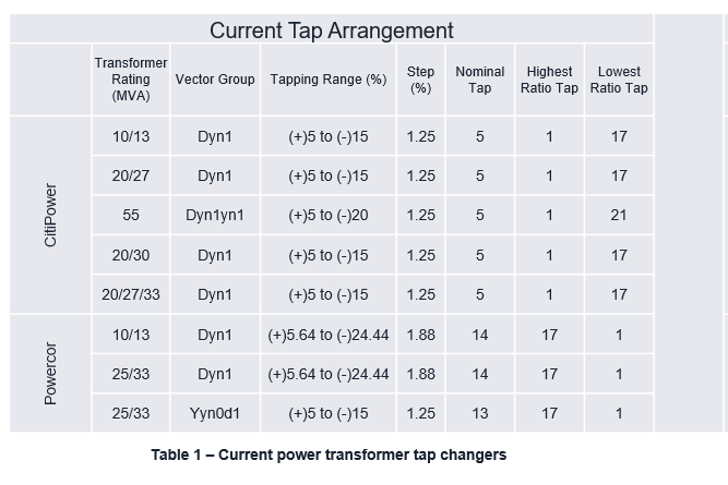
Tap settings are applied based on the rating or vector group depending on what part of the network the Transformer is located. For Citipower substations the NAME_PLATE_RATING dictates the tap settings that are applied, whereas for Powercor substations the vector group dictates the tap settings.
Tap settings get applied based on vector group/rating as follows:
Sample content:
ID,SUBSTATION_NAME,NAME_PLATE_RATING,VECTOR_GROUP
10297282,SK,27,Unknown
10297293,BAN,30,DY1
10297304,BAS,30,DY1
10297310,SK,30,DYN1
Line Regulator Settings file
Structure:
Regulators,CT_Ratio,VT_Ratio,Set_Point,Bandwidth,Resistance,Reactance,CT_Primary,Time_Delay,Reverse_Resistance,Reverse_Reactance
<Transformer Name>,<float>,<float>,<float>,<float>,<float>,<float>,<float>,<float>,<float>,<float>
Matching is performed on transformer name via the Regulators column.
Sample content:
Regulators,CT_Ratio,VT_Ratio,Set_Point,Bandwidth,Resistance,Reactance,CT_Primary,Time_Delay,Reverse_Resistance,Reverse_Reactance
9723 ALLANSFORD REG,80,183.3,117,3,3,4,400,50,-3,-4
9724 ALLANSFORD REG,80,183.3,117,3,3,4,400,50,-3,-4
9725 ALLANSFORD REG,80,183.3,117,3,3,4,400,50,-3,-4
ANNUELLO ROAD P47 REG,40,183.3,118.2,3,5.4,4.3,200,80,0,0
ANNUELLO ROAD P47 REG 1,40,183.3,118.2,3,5.4,4.3,200,80,0,0
Voltage Regulator Settings file
Structure
Same structure as above except with 2 less columns and Substation mRIDs rather than transformer names as a key.
Station,CT_Ratio,VT_Ratio,Set_Point,Bandwidth,Resistance,Reactance,CT_Primary,Time_Delay
<SUBSTATION_MRID>,<float>,<float>,<float>,<float>,<float>,<float>,<float>,<float>
Sample content:
Station,CT_Ratio,VT_Ratio,Set_Point,Bandwidth,Resistance,Reactance,CT_Primary,Time_Delay
AC,300,100,112.2,10,0,0,1500,100
AL,300,100,111.1,1.2,4.4,4.4,1500,100
AP,300,100,113.9,1.1,,,1500,100
AR,300,100,112.2,1.1,2.2,3.1,1500,100
ART,100,200,110,2,4.8,3.6,600,100
Source Impedance file
Structure CPPAL
Bus,TS,Name,kV,3PH.kA,LG.kA,LL.kA,thev.r1,thev.x1,thev.r0,thev.x0,Limit,Column1
<Bus ID (unused): string>,<Substation names (unused): string>,<Substation mRID (whitespace) Voltage>,<integer>,<float>,<float>,<float>,<float>,<float>,<float>,<float>,<float (unused)>,<string (unused)>
Sample Content CPPAL:
Bus,TS,Name,kV,3PH.kA,LG.kA,LL.kA,thev.r1,thev.x1,thev.r0,thev.x0,Limit,Column1
38015,ATS-BLTS,AC 11,11,19,20.4,16.4,0.02,0.342,0.008,0.269,18.4,VEDC
36015,ATS-BLTS,AC 66,66,15.3,12.5,13.3,0.286,2.641,0.436,4.282,21.9,VEDC
38017,ATS-BLTS,AL 11,11,7.6,9.1,6.5,0.021,0.908,0.012,0.416,18.4,VEDC
36017,ATS-BLTS,AL 66,66,14.8,11.4,12.8,0.322,2.732,0.559,4.95,21.9,VEDC
38221,FBTS,AP   11,11,15.7,15.7,13.6,0.018,0.451,0.014,0.423,18.4,VEDC
36221,FBTS,AP   66,66,15.9,11.2,13.8,0.237,2.539,0.483,5.415,21.9,VEDC
Structure EE
Substation,FaultedBus,Bus,BasekV,SLG_A,TPh_A,Rpos,Xpos,Rneg,Xneg,Rzero,Xzero,RevDate,EditedBy,Comment
<Substation mRID (whitespace) Substation name: string>,<(unused) string>,<(unused) string>,<(unused) string>,<(unused) float>,<(unused) float>,<float>,<float>,<float>,<float>,<float>,<float>,<float>,<(unused) string>,<(unused) string>
Sample Content EE:
Substation,FaultedBus,Bus,BasekV,SLG_A,TPh_A,Rpos,Xpos,Rneg,Xneg,Rzero,Xzero,RevDate,EditedBy,Comment
ADA ADAMINABY,6746,ADA033A,33.0,1040.0,885.7,5.34531,20.8363,5.34467,20.8384,1.10689,12.0062,6/06/2018,,some comment
ADA ADAMINABY,6732,ADA011A,11.0,3524.3,3014.4,0.49526,2.04778,0.49522,2.04786,0.05294,1.20884,4/10/2016,,another comment
ADE ADELONG,11465,ADE011A,11.0,2253.0,2153.6,0.36771,2.92594,0.36761,2.9272,0.15179,2.55666,7/04/2011,,S.East Rpt: TFR 1 upgraded to 3MVA
AFD ASHFORD,11784,AFD022A,22.0,923.7,878.1,1.849585,14.346209,1.858122,14.357422,0.858186,12.295956,21/09/2010,,Original Issue
Span Ratings file
Structure
GIS_Segment_ID,Span_ID,Feeder_ID,Span Voltage,Conductor Type,Neara_T,Neara_I
<unused string>,<string>,<unused string>,<unused string>,<unused string>,<int>,<float>
Sample Content
GIS_Segment_ID,Span_ID,Feeder_ID,Span Voltage,Conductor Type,Neara_T,Neara_I
2236668,5364487,FDR12,11kV,STEEL 3/2.75,50,22.19
2236668,5364486,FDR12,11kV,STEEL 3/2.75,50,22.19
7651645,6301790,FDR12,11kV,STEEL 7/16 (7/0.064),50,19.68
388296,5134033,FDR12,11kV,GOPHER 6/1/2.36,67,121.4
388296,5134032,FDR12,11kV,GOPHER 6/1/2.36,50,70.86
Tap Settings file
Structure CPPAL
ID,Tx Nominal Tap No.,Tap Position,Highest Tap Step (Max Boost),Lowest Tap Step (Max Buck),Control Enabled,RatioTapChanger.stepVoltageIncrement
<integer>,<integer>,<integer>,<integer>,<integer>,<boolean>,<double -1..1>
Sample Content CPPAL:
ID,Tx Nominal Tap No.,Tap Position,Highest Tap Step (Max Boost),Lowest Tap Step (Max Buck),Control Enabled,RatioTapChanger.stepVoltageIncrement
19981169,4,1,8,1,FALSE,0.025
#N/A,4,2,8,1,FALSE,0.025
20320900,4,2,8,1,FALSE,0.025
94723101,4,3,8,1,FALSE,0.025
Structure EE
sub_label,tx_nominal_tap_num,tap_position,highest_tap_step_max_boost,lowest_tap_step_max_buck,control_enabled,step_voltage_increment
<string>,<integer>,<integer>,<integer>,<integer>,<boolean>,<double>
Sample Content EE:
sub_label,tx_nominal_tap_num,tap_position,highest_tap_step_max_boost,lowest_tap_step_max_buck,control_enabled,step_voltage_increment
substation_site111753,5,5,8,1,FALSE,2.5
substation_site111754,5,5,8,1,FALSE,2.5
substation_site111755,5,5,8,1,FALSE,2.5
substation_site111757,5,3,8,1,FALSE,2.5
Area Objects file
GeoJSON files containing features.
Structure and Content.
{
    "type": "FeatureCollection",
    "name": "substation",
    "features": [
        {
            "type":"Feature",
            "id":"mRID0987654321",
            "id":"mRID0987654321",
            "geometry":{
                "type": "Polygon",  -- required to be a Polygon for this processor
                "coordinates": [  -- mapped to the location points of the AreaObject
                    [
                        [104.231827363,-36.2436789733],
                        ...
                    ]
                ]
            },
            "geometry_name":"COVERAGE",
            "properties":{
                "ID": 10897196,
                "TYPE":"indoor",
                "STATUS":"in service",
                "OPERATIONAL_LEVEL":"Distribution LV Supply",
                "KNOWN_AS":"mRID123456789"
                ...
            }
            ...
        },
        {
            ...
            // more features
            ...
        }
    ]
}