Application Landing Page
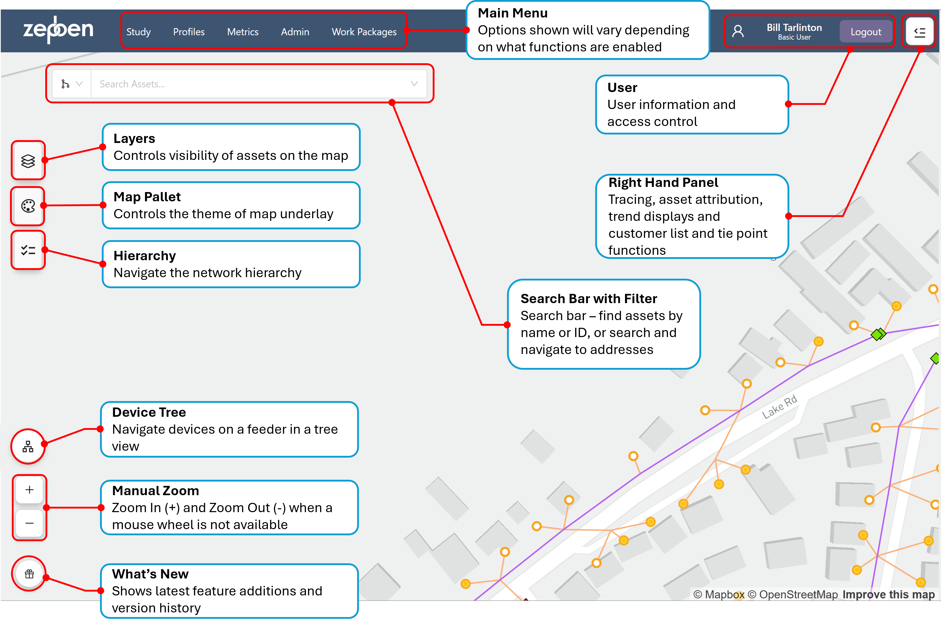
The application landing page shows a map of the network. The default location and zoom level the map is opened at can be set by the system administrator.
This screen shot above shows the map with a portion of the network visible. The functions of the various controls on the landing page are described in the callouts that have been overlaid on the map.
The symbols representing the “point” assets such as transformers and switches can be changed through configuration by the system administrator, allowing for consistent symbology with other corporate systems to be implemented within Network Explorer. This extends to being able to change the symbol for different sub-types of the same asset types. For example, a switch could have a different symbol for a fuse, circuit breaker and disconnector, and these could be different at each voltage level.
Switching devices can also be given different symbols based on their open and closed states, allowing easy identification of normal device state on the maps.
Each device displays its operational name beneath the device icon. These names follow organisation-specific naming conventions, which can be configured by the system administrator.
The conductors, shown in this example as lines coloured by voltage, will show solid lines for overhead conductor and dotted lines for underground conductors. The conductors can be coloured by voltage level, phase, feeder or impedance via the layers control.
Selecting Assets
As you move the mouse around on the map, the mouse pointer will be displayed as an open hand until it comes into proximity to one or more assets. The mouse pointer will then be displayed as a hand with a pointed finger. If you click the left mouse button now, you will get a menu that allows you to select nearby assets, as illustrated in the screen shot below.
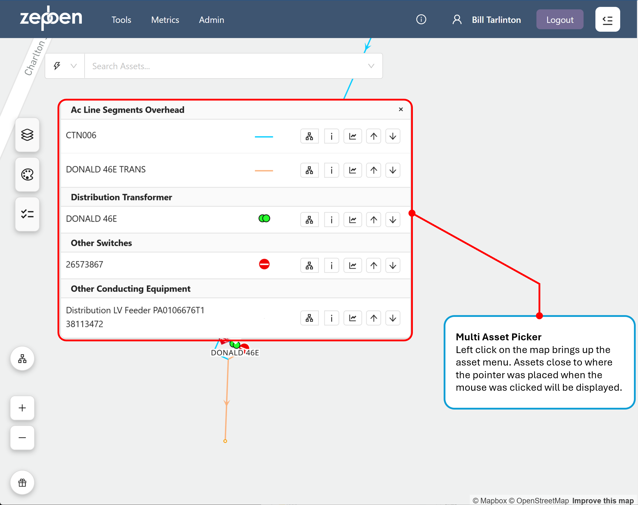
If you left click on the map with the pointed finger icon visible at a highly zoomed out level, you may get many assets displayed in the pop-up menu. The more you zoom in, the less "hits" you will get.
The buttons associated with each of the icons in the screen shot above perform the following functions.
Button | Action performed |
|---|---|
 | Opens the left hand panel, and show the device tree. See Device Tree |
 | Opens the right hand panel, and show information about the asset. See Asset Details Tab |
 | Opens the right hand panel, and show a load trend for all assets connected downstream of the selected asset. See load trends tab |
 | Performs an upstream trace from the asset, stopping by default at the feeder head. See Upstream Trace |
 | Performs a downstream trace from the asset. See Downstream Trace |
 | Adds or removes an isolation point when performing isolation traces. See Isolation Trace |
Panning and Zooming
With the open hand icon displayed, the network map can be panned by holding down the left mouse button and moving the mouse, or by using touch controls on tablet devices.
The network map can be zoomed in an out by using the scroll wheel, or by using the + and – buttons on the bottom left of the map page.
As the network map is zoomed in and out, various symbols will turn on and off to declutter the network view. For instance, important devices like reclosers in the medium voltage network may show at more zoomed out levels than less important devices like fuses in the LV network.
The zoom level at which devices turn on and off can be configured by your system administrator. The perspective and orientation of the map can also be changed by holding down the right mouse button and moving the mouse up or down (for aspect ratio) and left to right (for orientation).
The video clip below shows how the various zoom, pan, orientation and aspect ratio functions are used with the map.