Asset Details
The Asset details is a tab on the right hand panel, and provides additional information about a specific asset selected from the map or device tree.
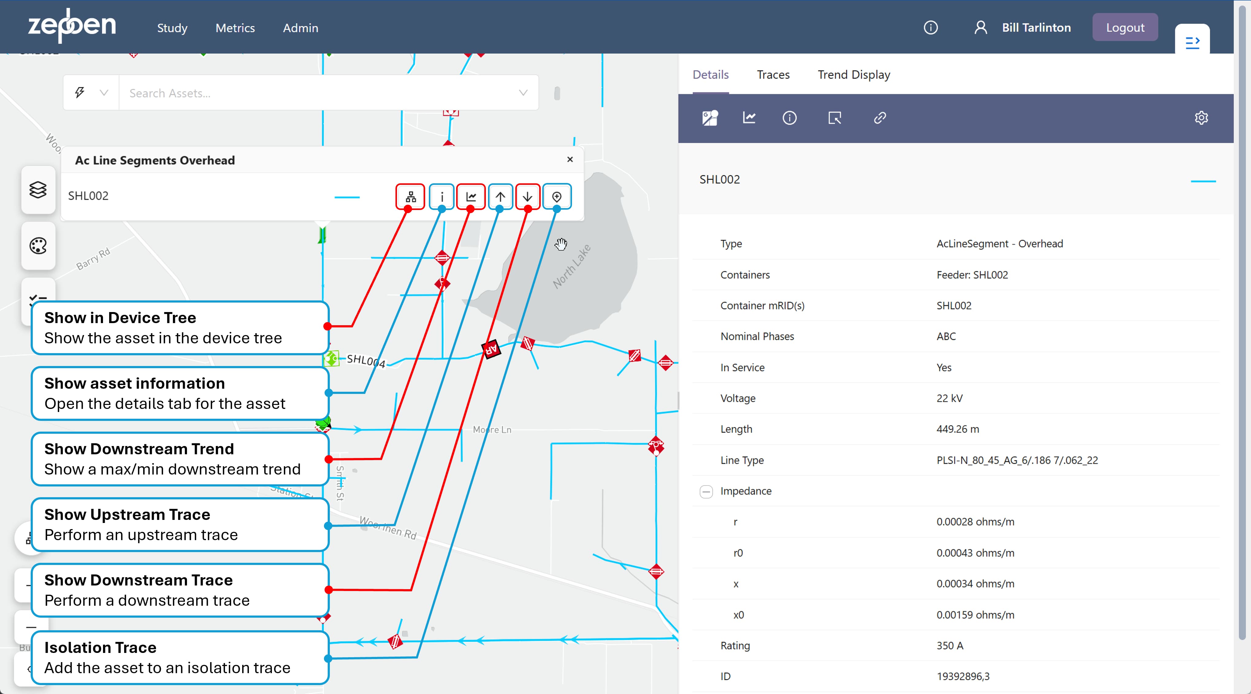
Details tab
An example of a details tab is provided in the screen shot below, along with an explanation of the various actions available from the asset menu.
Details Header
A header on the top of the Details panel, as shown in the screen shot below, provides various useful functions and options.
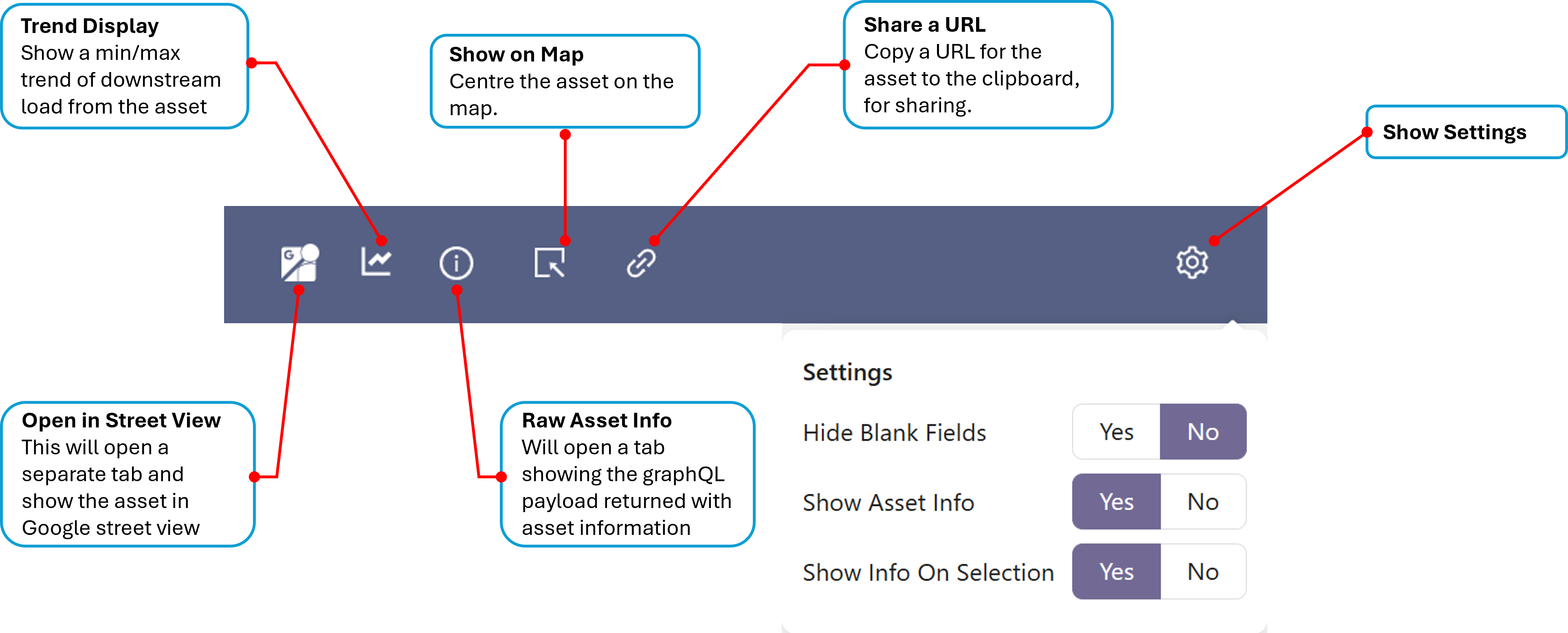
Open in Street View
As the same suggests, this button will open a new browser tab and using the geo-coordinates (latitude and longitude) of the asset in the details panel, attempt to show the asset in Google street view.
The street view will only succeed if there is a street view close to the co-coordinates of the selected asset. If you pick an overhead conductor in the middle of a field, for instance, its unlikely you will be able to obtain a street view of the asset.
Trend Display
This will open the trend panel and show a min/max downstream load trend for the currently selected asset. See downstream trends
Raw Asset Info
This will show information about the asset as delivered to the Network Explorer client. This contains information that is useful to debug data issues, and may contain additional information not displayed in the tabular attributes displayed in the panel.
Show On Map
If you have panned away from the asset on the map, pressing this button will re-centre the map on the asset.
Share a URL
This will create a URL which will allow you to share the assets details with someone else, if they simply paste the link into their own browser. The link will open the Network Explorer app, centre the map on the asset passed as a parameter and open the asset Details tab for the asset.
https://prod.your-org.zepben.com/?asset=%7B%22id%22%3A%2223731460%2C3%22%7D
Settings
The options available in the Settings dialog is shown in the screen shot below.
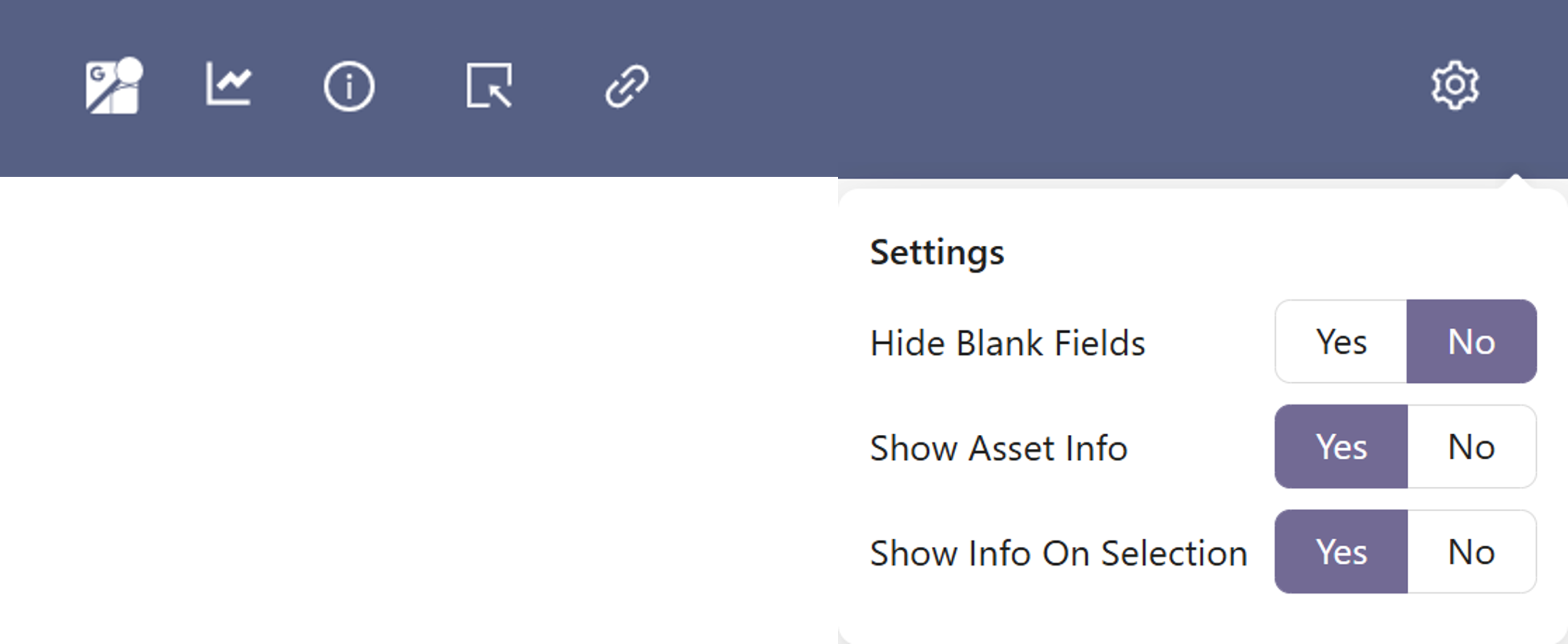
- Hide Blank Fields - if this is set to "Yes", attributes with no value will not be shown in the list of attributes
- Show Asset info - will show or hide the icon to show raw asset info
- Show Info On Selection - will automatically update the details tab to assets as they are selected
Explanation of asset attributes
The underlying asset model used by the Energy Workbench is the IEC Common Information Model (CIM). For those readers interested in which parts of the CIM have been implemented in the Energy Workbench, follow this link
Although the Energy Workbench supports a wide range of asset attribution, not all of this may be captured for an Energy Workbench deployment, and not all of it is exposed in the Details panel
The assets details will include the following information for each asset type displayed on the map, where available:
| Attribute Name | Present in | Description/Explanation |
|---|---|---|
| asset ID | all assets | this is unique ID, which is typically an integer obtained from the asset model source system. It may also be an alpha-numeric text string, depending on how ID’s are constructed in the source system |
| name | all assets except conductors | this is typically used to identify the asset in the field, with a physical label with the name attached to the asset. The name can also be used to search for the asset in the asset search tool. The asset name is displayed as a header field in the Details panel for node assets like switches, poles and transformers |
| type | transformers, switches and conductors | A switch can be one of a fuse, breaker, disconnector, recloser or jumper - This is obtained from the actual switch class defined in the IEC CIM. Transformers can be one of a Zone Transformer, Distribution Transformer, Isolation Transformer or Regulator – this is obtained from the transformer function attribute in the IEC CIM. |
| Line Type | conductors | This is a field that provides a code for the type of line, which is used to lookup impedance and rating characteristics. This may or may not be set, depending on whether this attribute is available in your deployment. |
| Description | all assets | This will often have not value, but it may be used to display additional information about the asset which does not fit naturally in any other fields. For example, the description could have information about the material used for a conductor, or a sub-type of a recloser. This attribute is dependent on how the network model has been built from source systems |
| Nominal Phases | Conductors, Switches and Supply Points | This shows what phases the asset has. It is not shown on transformers because phasing can change on each winding of the transformer. The conductors connected to each of the transformers windings define how the transformer treats phases on each winding. |
| asset container(s) | all assets | This will be either the HV Feeder or the LV Circuit the asset is contained by. This field is not available for objects contained by a Zone Substation or EHV circuit in this release of the software but may be in future. Normally open switches between two feeders in the distribution network will have the two feeders or circuits either side of the switch as containers. |
| Voltage | all assets | This is the operating voltage of the asset, not the voltage level, as described here. For transformers, a separate voltage is provided for each winding (or transformer "end"). Like Nominal Phase, the Voltage is calculated at run time based on information in source systems. The algorithm that does this guarantees the creation of an electrically correct model. If a voltage level cannot be determined for an asset, it will be treated as having an unknown voltage |
| Length | conductors | This is the length of the conductor - this is generally taken directly from source systems |
| Impedance | conductors and transformers | This contains electrical impedance data. Another table is provided below that has a description of the impedance fields. On transformers, impedance data is provide for each transformer winding (or "end"). |
| Design Temperature | conductors | This is a value that is typically used by planning engineers. It may or may not be populated, depending on whether it has been included in the network model data. |
| Design Rating | conductors and switches | This is the rated design current for the asset, expressed in Amps |
| State | switches | The normally open or closed state of the device. |
Additional notes on asset attribution
- The Nominal Phases of an asset is calculated by an algorithm that considers available phase information in the source system(s) and attempts to create phase information that is electrically consistent and has the highest chance of being correct. This is because the phase information in source systems is often anomalous and/or only partially populated.
Impedance data
The following table describes the impedance data for conductors
| Impedance field | Description/Explanation |
|---|---|
| r | Positive sequence series resistance, in ohms per meter |
| r0 | Zero Sequence series resistance, in ohms per meter |
| x | Positive sequence series reactance, in ohms per meter |
| x0 | Zero sequence series reactance, in ohms per meter |
| b0ch | Zero sequence shunt (charging) susceptance, in siemens per metre (SPerm) |
| bch | Positive sequence shunt (charging) susceptance, in siemens per metre (SPerm) |
| g0ch | Zero sequence shunt (charging) conductance, in siemens per meter (SPerm) |
| gch | Positive sequence shunt (charging) conductance, in siemens per meter (SPerm) |
The following table describes the impedance data for transformer windings (or ends)
| Impedance field | Description/Explanation |
|---|---|
| r | Resistance (star-model) of the transformer end, in ohms |
| r0 | Zero sequence series resistance (star-model) of the transformer end, in ohms |
| x | Positive sequence series reactance (star-model) of the transformer end, in ohms |
| x0 | Zero sequence series reactance of the transformer end, in ohms |
| b | Magnetizing branch susceptance (B mag). The value can be positive or negative, in siemens (S) |
| b0 | Zero sequence magnetizing branch susceptance, in siemens per metre (S) |
| g | Magnetizing branch conductance, in siemens (S) |
| g0 | Zero sequence magnetizing branch conductance (star-model), in siemens (S) |
| Phase Angle Clock | Terminal voltage phase angle displacement where 360 degrees are represented with clock hours. The valid values are 0 to 11. For example, for the secondary side end of a transformer with vector group code of 'Dyn11', specify the connection kind as wye with neutral and specify the phase angle of the clock as 11. The clock value of the transformer end number specified as 1, is assumed to be zero. Note the transformer end number is not assumed to be the same as the terminal sequence number. |