Tracing
The Tracing tab is on the right hand panel.
The tracing tab
Tracing takes advantage of the network connectivity model in the Energy Workbench to allow assets to be traced to form a set of assets related by connectivity. Once the trace is performed, various functions are provided to
- Highlight the traced assets on the map, including being able to zoom to the extent of the trace,
- Display metrics about the set of assets included in the trace,
- Create a list of customers connected to the traced asset, and
- Create a list of tie points, where a trace stops at the terminal of an open switch which has a conductor on another feeder connected to its other terminal.
Only assets that are part of the connectivity model will be found in a trace. Poles are support structures only – not part of the electrical model and will not be found in a trace.
Opening the Traces Tab is done by clicking the “Traces” tab in the Right Hand Panel, as illustrated in the screen shot below. If no asset has been previously clicked on in the map, the tab will open with no asset shown. Any asset clicked on the map will be displayed by default in the trace window when it opens.
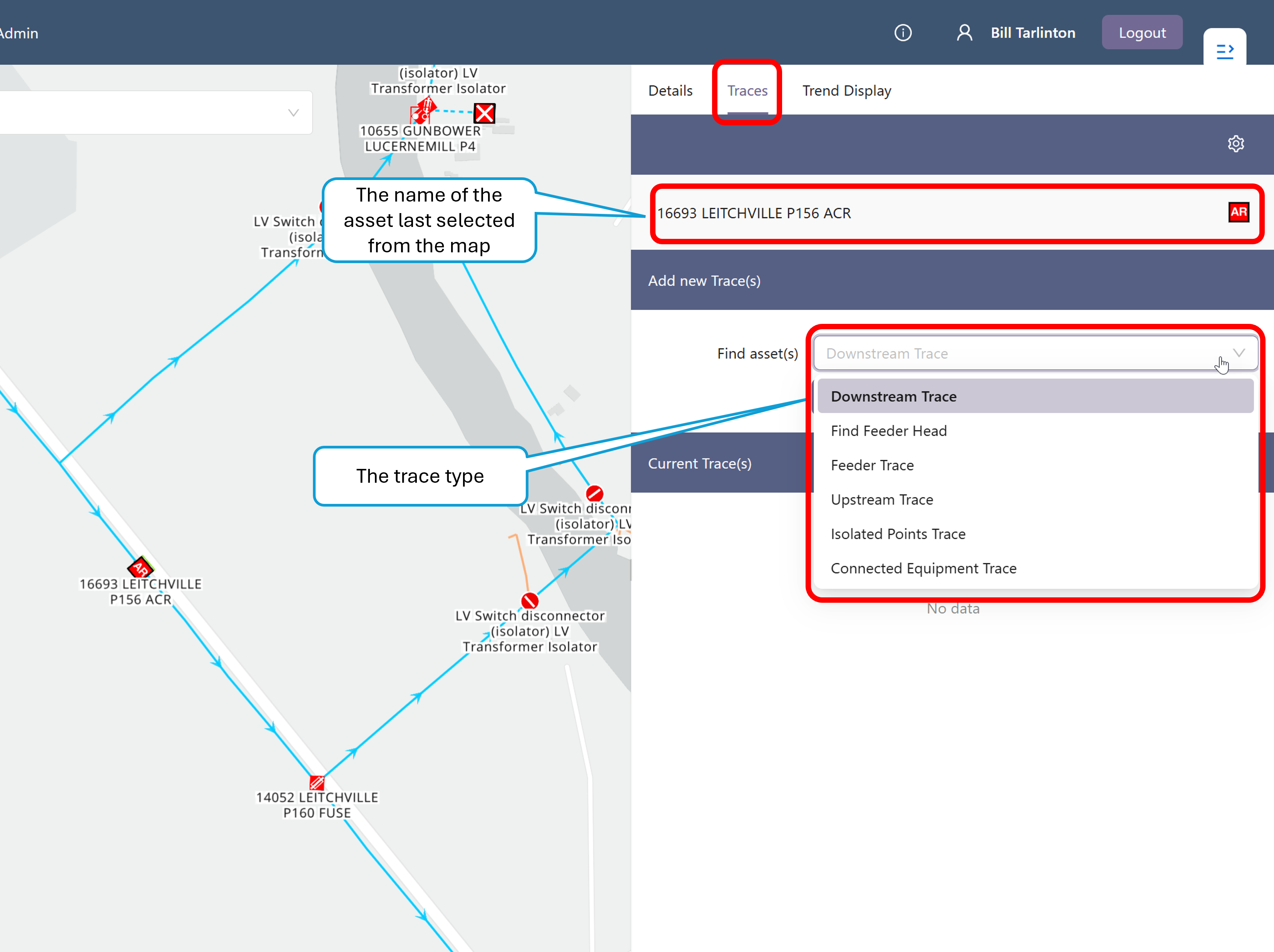
Traces may be initiated using point assets (transformers or switches) or conductors. If a point asset is clicked in the map, the name of the asset will be displayed in the trace panel for the currently selected asset. If a conductor is picked, the conductor’s feeder will be displayed. The format of the asset and conductor feeder names will differ in each deployment, depending on conventions used by your organisation.
Network tracing generally only works on the radial distribution network, that is, the HV and LV network levels, as it relies on knowing the nominal direction of power flow. The one exception is the Connected Equipment Trace, which works on the EHV network as well, and is described in more detail below.
The trace type can be one of the following.
- Downstream Trace
- Find Feeder Head
- Feeder Trace
- Upstream Trace
- Isolated Points Trace
- Connected Equipment Trace
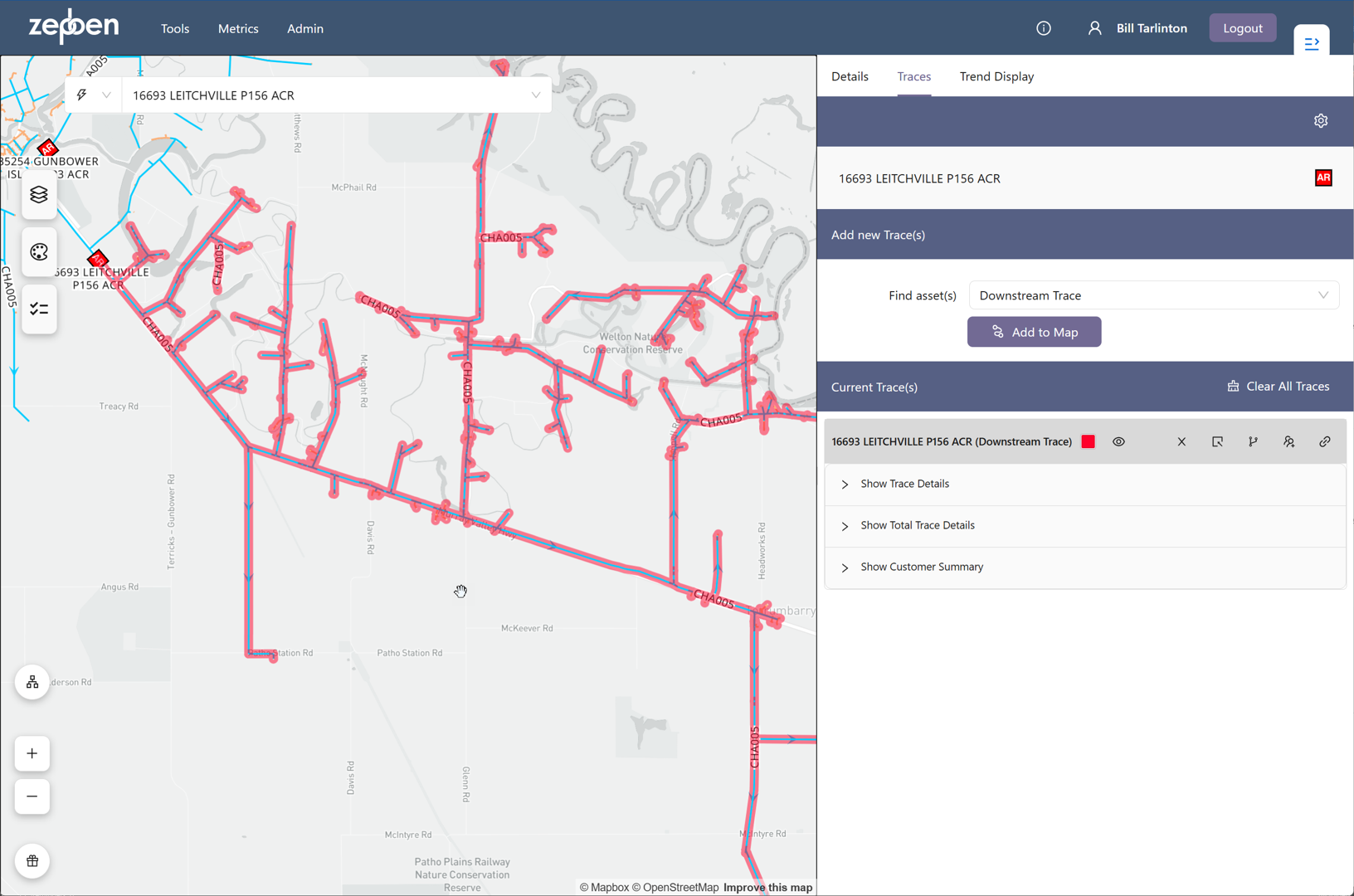
Downstream Trace
A downstream trace will traverse the network that is downstream from the selected asset. Downstream means the direction away from (downstream of) the primary supply source for the asset. Pressing the “Add to Map” button will produce a display that looks something like the screen shot below. In this example, the user has requested a downstream trace starting from the recloser "16693 LEITCHVILLE P156 ACR".
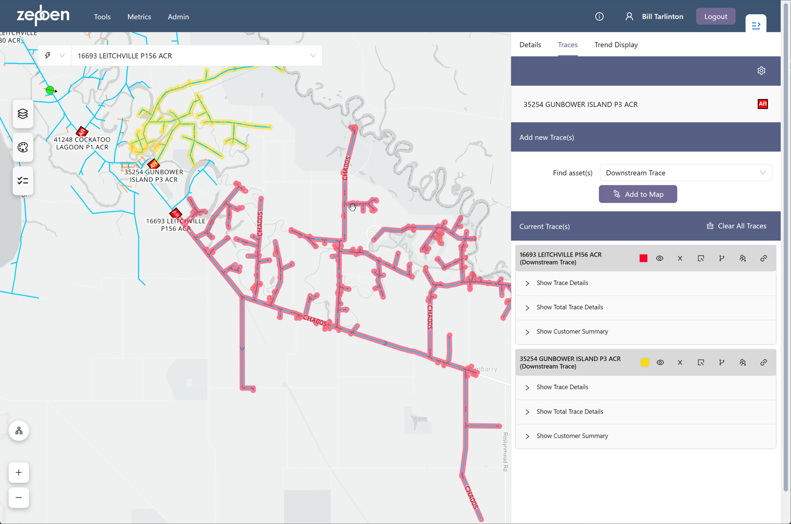
More than one trace can be added to the map, when this is done, the colour of the trace will rotate through a pallet of colours. The screen shot below shows two downstream traces on the same map.
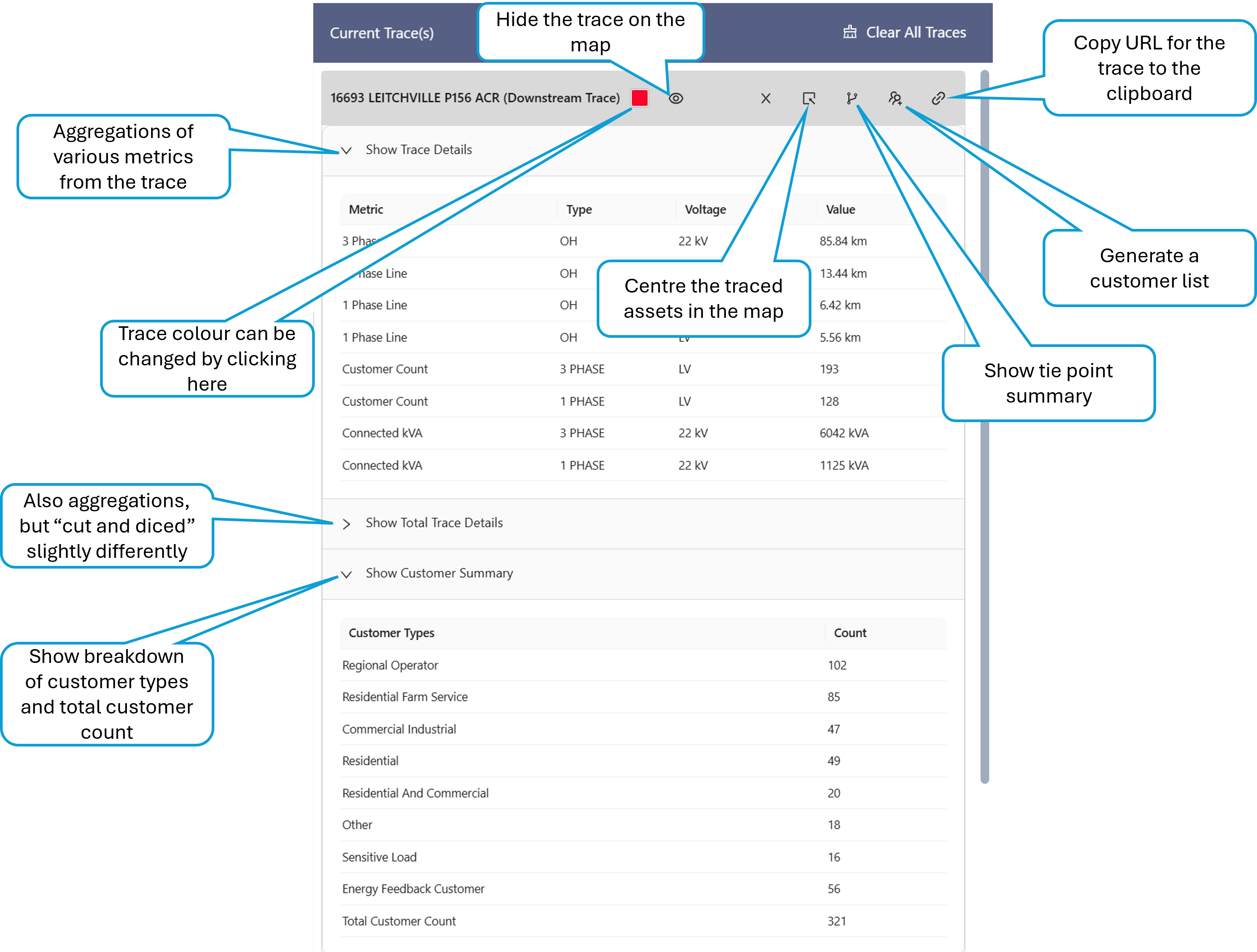
The colour of the traces can also be changed by clicking on the coloured square adjacent to the name of the trace. Each trace has various additional actions, as illustrated in the screenshot below. These are common to all trace types.
Find Feeder Head
If invoked from an asset in the HV network, this trace will find the device supplying the HV feeder. This is normally the circuit breaker in the Zone Substation protecting the feeder.
If invoked from an asset in the LV network, the trace will find the device supplying the LV feeder. This is normally the transformer of the distribution substation.
When the trace is "Added to the map", it will navigate to the head device on the map. There will be a circle drawn around it in the trace colour, and the selected asset for the details, traces and trends tabs will become that asset.
Feeder Trace
The Feeder trace will trace all assets both upstream and downstream of the selected asset.
If invoked from an asset in the HV network, the trace will find all assets connected to the HV feeder, including LV assets.
If invoked from an asset in the LV network, the trace will only find assets on the LV feeder of the asset the trace was initiated from.
Upstream Trace
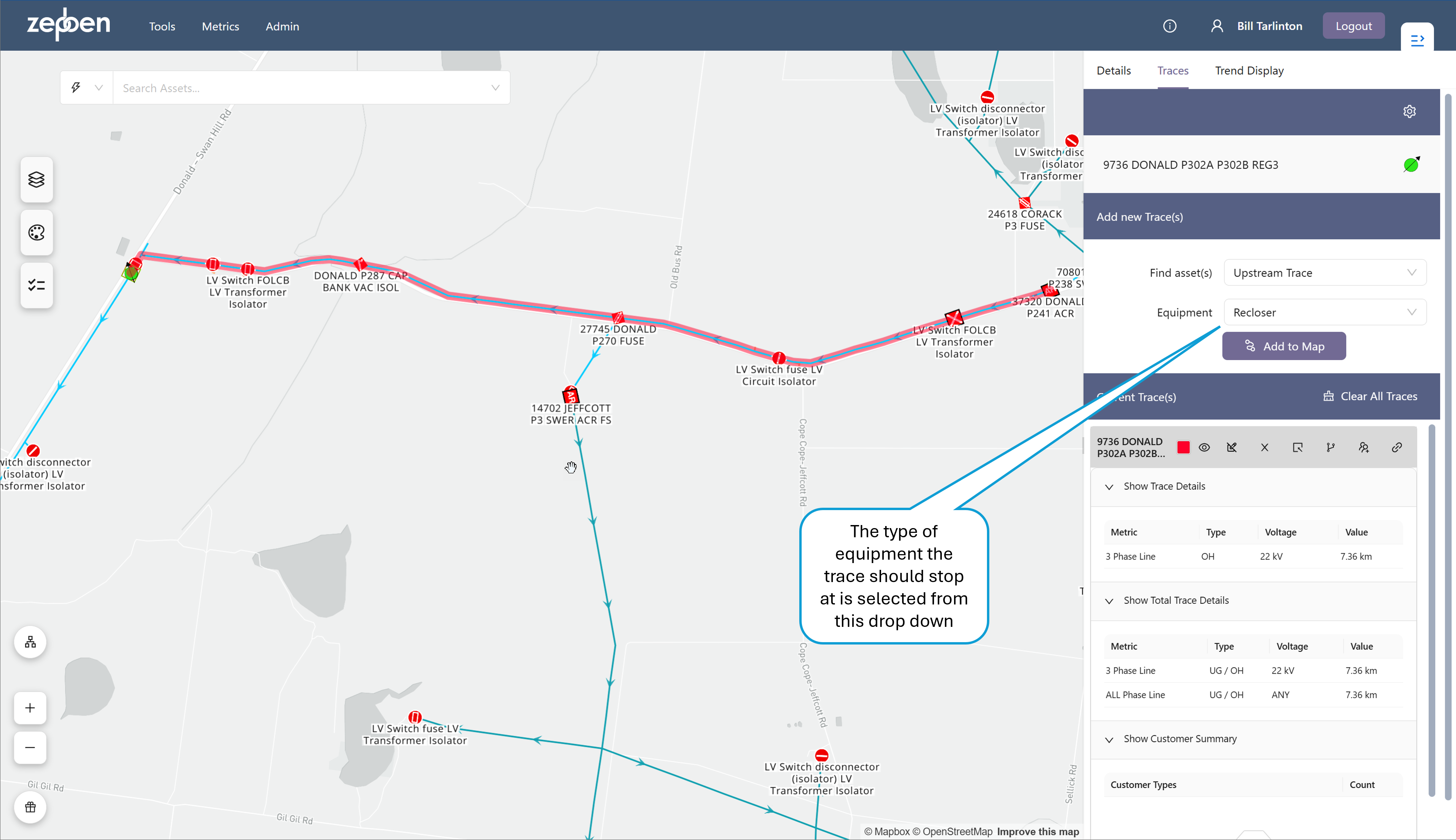
The upstream trace will trace assets in the upstream direction, and stop at an equipment type selected from a drop down list. Upstream means the direction toward the primary supply source for the asset
The following equipment types can be specified for the upstream trace to stop at.
- Feeder Head: In this trace, the trace will always stop the HV supply point for the network, even if the trace is invoked from an asset in the LV network. If you want to find the supplying transformer for the LV circuit, you can use the upstream trace to a Distribution Transformer.
- Any Switch: Any of the 5 switch types described below.
- Breaker: A mechanical switching device capable of making, carrying, and breaking currents under normal circuit conditions and also making, carrying for a specified time, and breaking currents under specified abnormal circuit conditions e.g. those of short circuit
- Recloser: A recloser is a Breaker that has a reclose function - that is that will automatically close after a short period if it trips due to a fault. These devices are often installed on Rural networks where trees can often fall on lines, causing a temporary fault that clears after the initial trip.
- Load Break Switch: A mechanical switching device capable of making, carrying, and breaking currents under normal (not fault) operating conditions.
- Fuse: An overcurrent protective device with a circuit opening fusible part that is heated and severed by the passage of overcurrent through it. A fuse is considered a switching device because it breaks current.
- Jumper: A short section of conductor with negligible impedance which can be manually removed and replaced if the circuit is de-energized.
- Any Transformer: Any of the three transformer types described below.
- Distribution Transformer: A transformer that provides the final voltage transformation for customer consumption in the electric power distribution system.
- Isolation Transformer: A transformer whose primary purpose is to isolate circuits - these are commonly used at the start of SWER lines.
- Regulator: A transformer that changes the voltage magnitude at a certain point in the power system to maintain voltage levels within code.
The five switch types in the list above correspond to leaf classes in the CIM object model, as described here. The three transformer types correspond to the TransformerFunctionKind, as described here
In this trace, only the route back to the nominated equipment type will be traced - any branches off this route will not be traced. The screen shot below shows an example upstream trace, where the recloser protecting the regulator "9736 DONALD P302A P302B REG3" has been found by performing an upstream trace from the regulator to an equipment typ of "Recloser".
Note also that the trace details for this type of trace cannot be used to find connected customers, as these are not connected in series with the main route conductors determined by the trace.
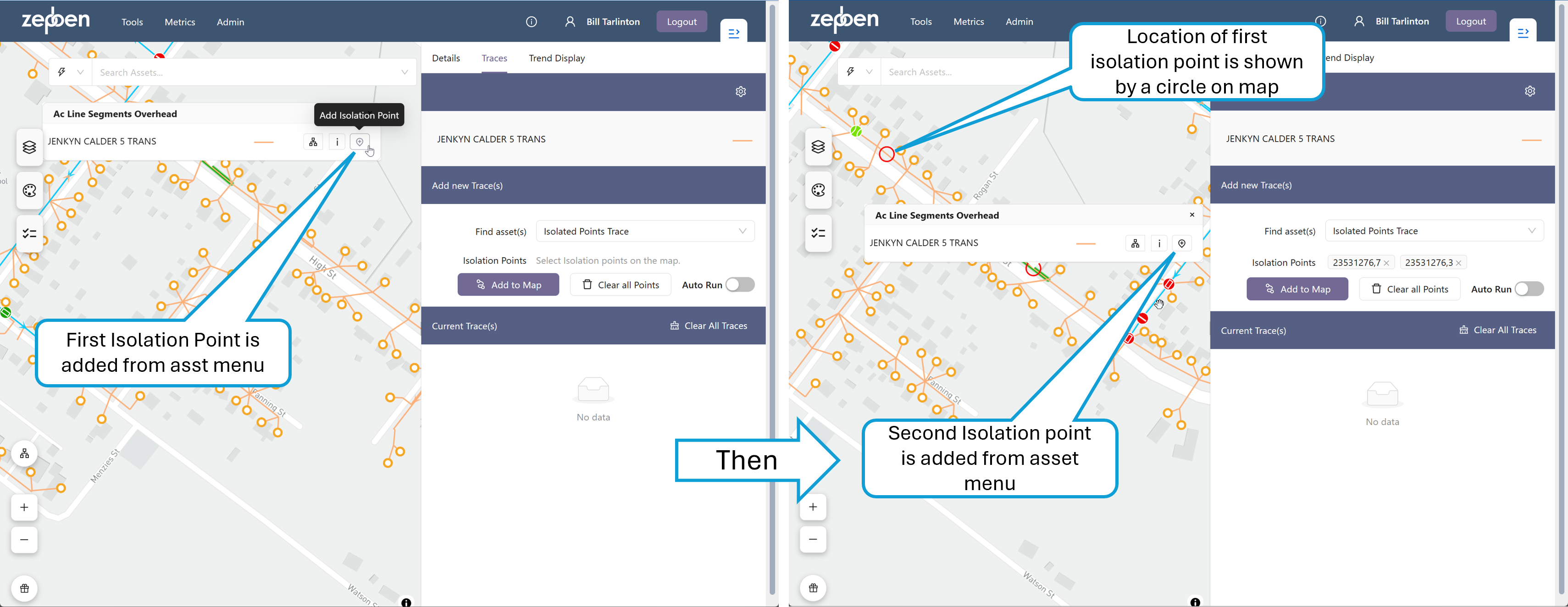
Isolated Points Trace
The isolated points traces allows you to "cut out" a part of the network and trace all the assets within this cut out network subset. This is done by specifying one or more boundary points that define the part of the network you want to select. When this trace type is selected, a new icon will be visible on the asset menu in the map, as illustrated in the screen shot below.
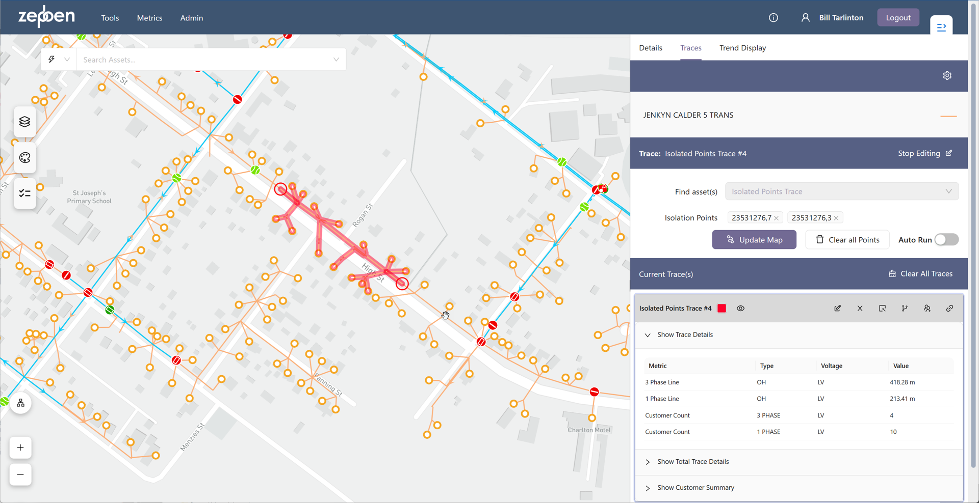
When the trace is added to the map, the network within the boundary points will be traced and highlighted, as illustrated in the screen show below. Once the trace is complete. Boundary points can be added anywhere along conductors, or can be added to switches and transformers. If a single boundary point is added to the map, the trace will act in the sam way as a Downstream Trace](#downstream-trace). If multiple boundary points are added to parts of the network that are not enclosed by those boundary points, the isolation traces formed by each of the sets of boundary points will be displayed on the map.
The Length values for the conductors in the details tab of the isolation point trace will show the total length of all conductor segments included in the trace - it will not take into account where along the conductor the boundary points are placed.
Connected Equipment Trace
The connected equipment trace will search the network by the number of steps specified in the "Steps" value, according to the direction specified. This trace will trace though open points, unlike other traces.